The need to simulate space
The current push to commercialize space travel has resulted in renewed demand to launch objects and even people into earth orbit or even deep space. Companies including SpaceX, Blue Origin and Rocket Lab have demonstrated the ability to make certain portions of a launch vehicle reusable and that may dramatically alter the cost to get to space. True rocket ship factories are emerging which, in one case, can put out a couple of full blown launch vehicles every month!
Demands for better telecommunication have created a market for small satellites – in some cases to be deployed as 'constellations'. Forecast are for hundreds, maybe thousands, of these CubeSats to be sent into earth orbit over the next few years. In addition, the International Space Station (ISS) is also used as a deployment platform for satellites. The ISS also requires re-supply of consumables and people on a regular basis.
Beyond the needs to get into earth orbit, there is still great interest in going further out—perhaps to return to the Moon or on to Mars. Pioneers such as Elon Musk have championed the idea of expanding the habitats for humans to include new planets like Mars and maybe beyond. Musk has been passionate about the concept of humans being a multi-planet species. He has said he wants to die on Mars – just not on impact! In the event of a colossal, life ending, calamity on Earth, the species will need someplace else to go.
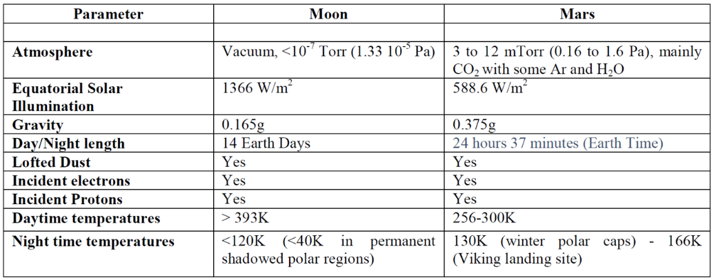
Table 1: Surface conditions on the Moon and Mars (Ref 1)
So this renewed rush to space has created the demand for a range of new gizmos that have to survive and thrive in the harsh conditions outside the earth's protective atmosphere. These conditions include: extreme vacuum; wide swings in temperature; exposure to high levels of radiation and dust; and bombardment by electrons and protons. The creation of this new fleet of space-bound products has created the need for a fleet of terrestrial systems to test components in conditions which mimic those of earth orbit and interplanetary travel.
The Moon, Mars and in between
Conditions on the Moon include a vacuum of 10-7 Torr and a range of temperatures from 40 Kelvin, in the permanently shadowed polar regions, to more than 393 Kelvin in full sun. Mars is considerably more hospitable, since it has not yet lost all of its atmosphere (mainly CO2 and some Ar and H2O). So atmospheric pressures there range from 3 to 12 mTorr with temperature swings between 130 and 300 Kelvin. The surfaces of both planets are subject to lofted dust particles, with incident electrons and protons. In transit from the Earth to Mars, vehicles will be in vacuum approaching 10-22 Torr.
Space on Earth
Space simulation systems (SSS), sometimes referred to as Thermal Vacuum Systems (TVAC), must be equipped to mimic the conditions of the Moon and Mars as best as is technically possible. Currently, using every available vacuum pump technology, the lowest pressure achievable on Earth is about 10-12 Torr – and that is only possible in perfectly engineered systems operated with heroic efforts. Simulation of the thermal conditions in space is more achievable as long as you have access to the world's supply of cryogenic nitrogen and helium with a very robust heating system.
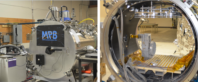
Figure 2: Space Simulation System designed to simulate conditions on Mars. (Ref 1)
Accordingly, components bound for space need to be vacuum ready. A component is considered vacuum ready, or vacuum clean, when it has no contaminants on its surface or absorbed into its interior which have a vapor pressure high enough to go to gas in the environment within the vacuum chamber. This type of contamination can include oils, lubricants, cleaning fluids, finger prints, high vapor pressure metals and plastics, cooling fluids, and others. This can also include microbial contamination from humans or from the assembly environment.
Certain gases are expected to emanate from a vacuum system during operation. Species like Ar, N2 and O2 are easily desorbed and pumped out of a vacuum system by the time it reached 10-7 Torr. Other gases, like CO2 , CH4 , CO, He, and H2 are much harder to pump. Water, too, is ubiquitous at almost any pressure so that, even at 10-9 Torr, the molecular density in a vacuum chamber is on the order of 32,000,000 molecules per cubic centimeter, where the dominant ape is hydrogen at 79% and water at 5%. If the vacuum system is sitting in a particularly polluted environment, such as the air surrounding my offices in Pittsburgh or Shanghai, then there may be H2S, NOx , Hg, Cd, SO2 , and other species, present.
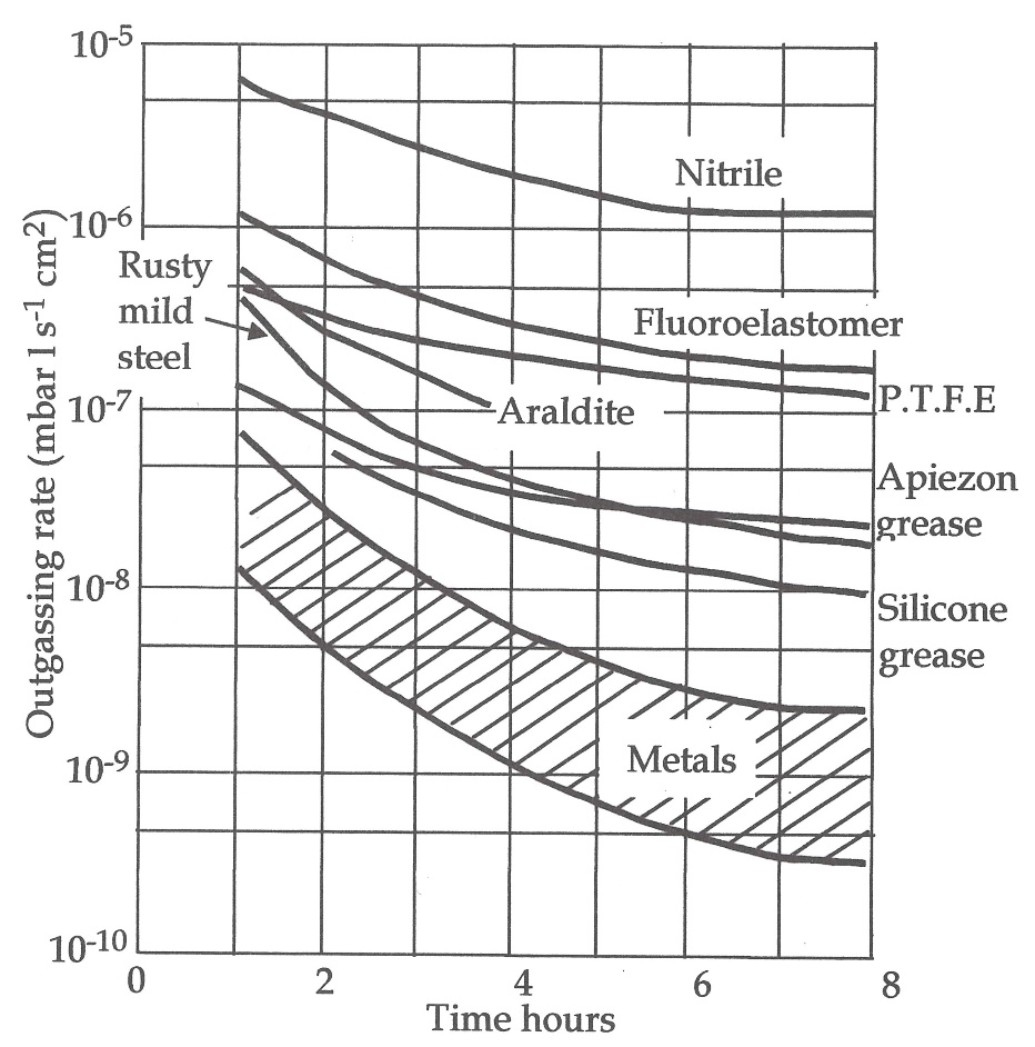
Figure 3: Generalized comparison of outgassing rates for polymers, metals and glasses, over time, in vacuum (Ref. 7)
In addition to pollutants from the air, contamination in vacuum systems can originate from sources including the pumping system, chamber construction materials, motion and manipulation fixtures, humans, and the payload. Through the basic gas-solid interactions of adsorption, desorption, diffusion, and permeation, molecules can migrate around a vacuum system. To the extent that pressure in a system is low enough to vaporize the contaminants listed above they add to the gas load of the system and may prevent it from achieving its designed operating conditions. This includes the sublimation of materials, like zinc metal, for example, which can become a vapor if the system temperature reaches 200°C and its pressure drops below 10-5 Torr. When a contaminant becomes a vapor it can also become a coating which can then put the payload or the vacuum system at risk and prevent vacuum readiness.
As an example of the extreme need for vacuum cleanliness, the allowable deposition rate for particulate on the interior surfaces of a Mars-bound spacecraft is on the order of 130 angstroms per year. So, if we assume that a water molecule is on the order of 2 angstroms in diameter, that is roughly a stack of only 70 mono-layers of water on a surface in a year.
Temperature variations within the TVAC system will also effect the behavior of gases, including vaporized contaminants. At low temperatures, some gases will condense, or adsorb, onto surfaces and be eliminated from the internal atmosphere, causing the pressure of the system to drop. But at high temperatures, those species are likely to desorb from surfaces and re-enter the gas load of the system. Over prolonged thermal cycling under continuous vacuum, it is likely that the ultimate base pressure of the system improves substantially.
Determination of the ultimate base pressure a system can achieve is a fairly straightforward calculation given by the following formula:
Gas Load / Effective Pumping Speed = Ultimate Base Pressure
In the case of a stainless steel box chamber, with dimensions of 100 x 100 x 100 cm, with an outgassing rate (for the steel) of 2 x 10⁻⁸ Torr.liters/cm2.sec and an effective pumping speed of 500 Torr.liters/sec, the ultimate base pressure is 2.4 x 10⁻⁶ Torr. If, in practice, the system will not achieve that pressure it has a leak or is contaminated.
For example, one finger print in a vacuum system can take 100 liters/sec off the pumping speed and be the difference between a base pressure of 10-7 Torr and 5 x 10⁻⁷ Torr – even after 10 hours of pumping. A fingerprint contains about 1019 particles. This is similar to a cubic centimeter of air, at 760 Torr and 23°C, which contains 2.4 x 10¹⁹ molecules.
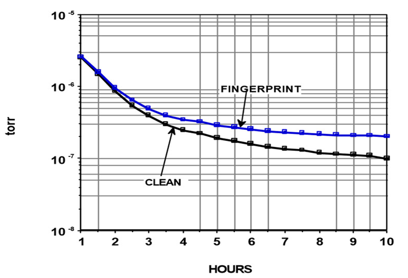
Figure 4: The impact of one fingerprint on the pump down time and ultimate pressure of a vacuum system (Ref 4).
Detecting contamination
In the event that a system is not able to achieve its ultimate base pressure, and it is not leaking, there are measurement approaches that will identify vaporized contaminants. One technique is called Residual Gas Analysis (RGA). The RGA is also called a Partial Pressure Analyzer because it can identify specific gas species and also quantify its contribution to the total pressure of the system. The system is based around a mass spectrometer that measures gas constituents and reports data in atomic mass units (AMU). In the case of a clean vacuum chamber pumped below 10-7 Torr, a typical scan will deliver peaks for molecular hydrogen, water, molecular nitrogen/CO/C2H4 , and CO2 with the sum of all of the partial pressures equaling the total pressure of the system.
Examples of contaminants include: Viton, or the constituents of that fluorocarbon compound, in the event that O-ring material has been overheated; vacuum pump oil that has back streamed into the chamber; and the solvent components in paints, such as emissivity coatings. However, since the system reports the presence of gases in AMU's the interpretation of RGA data can be difficult. Some species have similar AMU's and may overlap. In the words of one consultant brought in to interpret RGA data, "if you tell me what you put in the chamber I will tell you what the peaks mean." That can be a very frustrating answer when you do not know what went into the chamber – for example, a CubeSat made from a colossal collection of mysterious materials – many of which never were intended for application in vacuum.
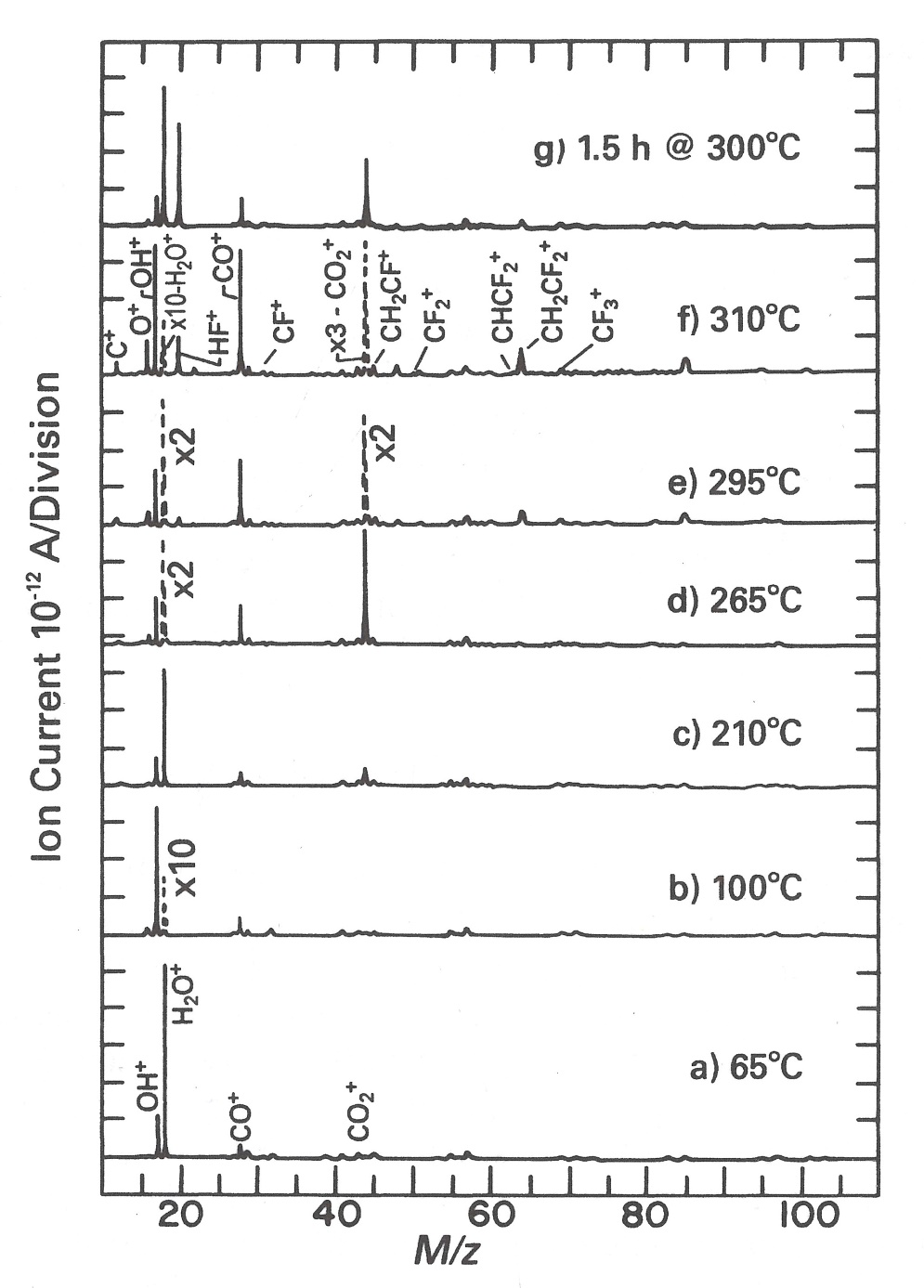
Figure 5: Residual Gas Analysis (RGA) scans of a vacuum system equipped with Viton O-rings at various temperatures (Ref. 3)
While the RGA is a great tool, most systems are pressure limited at 10-5 Torr, so if the combined partial pressures of the gas species in the system exceeds that pressure the instrument will protect itself and shut down. In some cases there may be a scenario where something in the system, likely some aspect of the payload, is vaporizing so much that its outgasses enough molecules to force the chamber pressure above the shut off limit for the RGA.
Another technique widely practiced in space simulation systems is the use of a Quartz Crystal Micro Balance (QCM). This device was developed to monitor the deposition rate of thin films in vacuum by processes such as sputtering and e-beam or thermal evaporation. Typically, in the thin film vacuum deposition technology for which these tools were developed, to measure a reasonable deposition rate, the vapor pressure of the evaporated material needs to be on the order of 10-4 Torr (or higher).
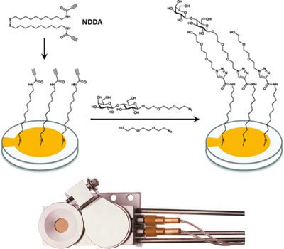
Figure 6: Examples of organic coatings on the single crystal sensor of a Quartz Crystal Micro (Ref 5)
As a film develops on the single crystal sensor of the instrument its characteristic vibration changes and that change, when calibrated to a specific material, can be interpreted as film thickness. In the case of QCMs in TVAC systems, typically the exact composition of the film that accumulates on the crystal is not known – as the exact type of contaminant condensing on the crystal is not known (or may be a mixture of contaminants) so this technique is basically a go/no-go as to whether there is or is not a vaporized contaminant in the system.
In the case where the payload or something else in the vacuum chamber, like the pumping system, is contributing a coating to the interior of the system, the gauges used to measure pressure may also be effected (by contamination). At very high pressures, from atmosphere (760 Torr) down to about 10-2 Torr, gauges that utilize a physical barrier between the gas environment being measured, such as the Bourdon, Piezo Resistance, Capacitance, and Diaphragm Manometer styles, can be used. These gauges are generally robust enough to handle some degree of contamination build up on their barrier structures. But gauges that use exposed filaments like the Convection/Pirani, Thermocouple, and Hot and Cold Cathode are vulnerable and may become inaccurate due to the presence of coatings on their sensing components.
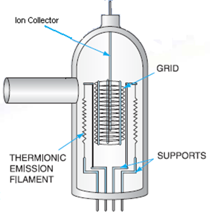
Figure 7: Diagram of a hot ion gauge showing the delicate filaments that are the source of the sensitivity of this approach (Ref: www.lesker.com)
Case study on a poorly designed and operated TVAC system
We recently worked with a client who was developing CubeSats and needed to test the devices prior to launch. They came to us piecemeal and bought gauges, pumps and some hardware without explaining their application in the entirety. Consequently, we were not able to offer any design or operation advice to their project prior to their initial tests. However, with the system assembled and the chamber empty they found they could reach a reasonable pressure in an acceptable amount of time.
But after the initial pumping trials they added the typical heating/cooling system, including a large platen to which they could attach up to four CubeSats. The addition of the thermal stage dramatically degraded the vacuum performance of the system. Further, when they added some CubeSat mock-ups they were no longer able to achieve a reasonable pressure even after several days of pumping. As the supplier of the pumps and gauging we were immediately accused of providing faulty equipment.
As we started to finally exchange information on their application we were able to quickly determine that they had not used good vacuum practice in the design of their thermal stage and they were not aware of the heroic measures required to maintain vacuum cleanliness. Their design of the thermal stage include several electric heaters which had large trapped volumes of ambient air and extensive runs of multi-strand insulated wiring. So they mistakenly engineered many large virtual leaks into the system. In addition to their design errors, they also handled all of the internal components, including their CubeSat mock-ups, with their bare hands, which applied approximately 1019 molecules of contamination for every finger print.
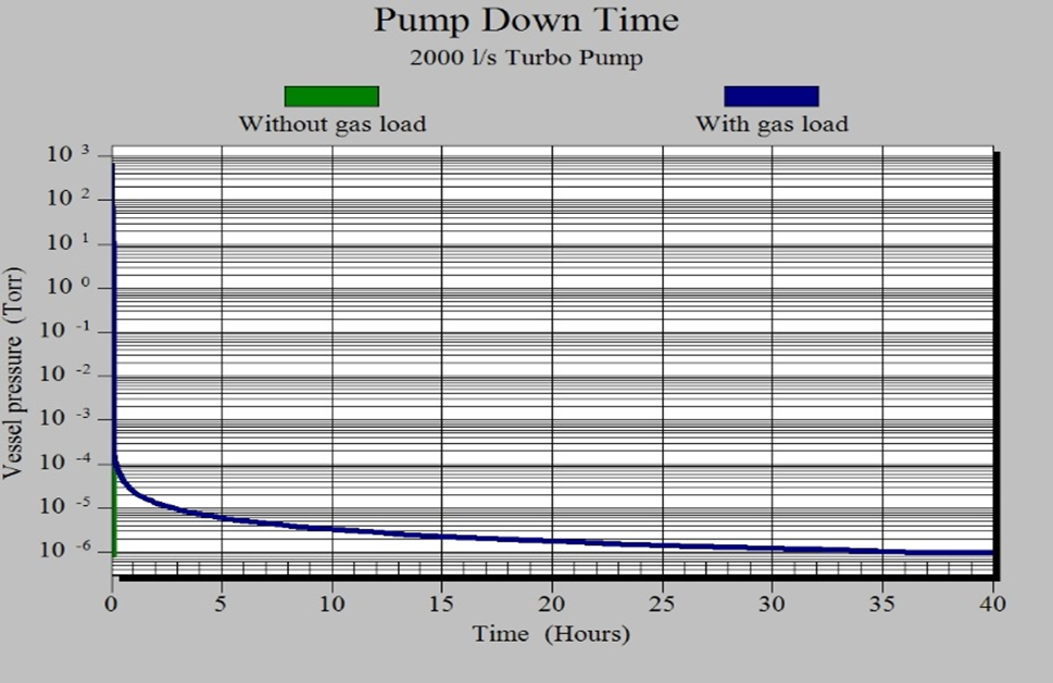
Figure 8: Pump down curve for pristine (green) Vs contaminated vacuum system (Ref Vactran)
In order to examine possible solutions we did computer simulations using their enormous gas loads with a variety of larger vacuum pumps, and it was clear early on that their only reasonable solution was to re-design the thermal stage (with the consultation of a reputable vacuum equipment manufacturer), completely dismantle and vapor degrease the entire vacuum chamber, and train their staff on good vacuum practice (wear gloves, don't breath on the chamber, keep it under vacuum when not in use, etc…)
Case study on great design and operation of a DTAVC system
In another example, we have recently worked with a company that has built a TVAC system which, in addition to typical vacuum and thermal capabilities, also included to ability to rain simulated Martian soil onto devices in the vacuum chamber. They call their system the Dusty Thermal Vacuum system or DTVAC. While we were not initially aware that our client was going to add dusting capabilities to their system, it was revealed when they did the final system acceptance in Pittsburgh. At that point they were warned that the system may not be able to achieve the same low pressures that they witnessed on our shop floor. With the enormous surface area added to the system with their powder delivery system and the powders themselves it seemed as if the additional gas load would likely swamp their pumping system.
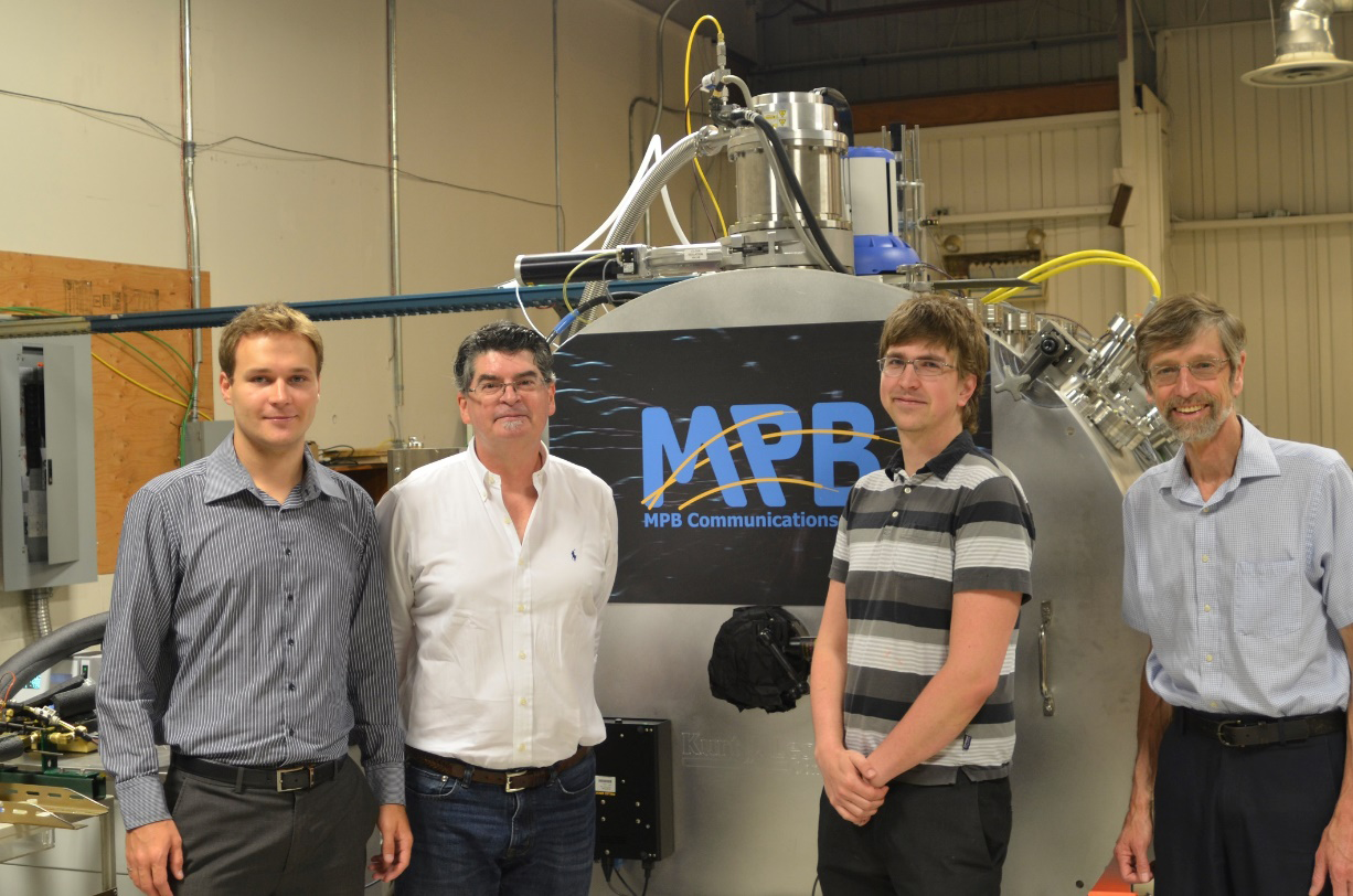
Figure 9: MPB and KJLC personnel in Montreal with the DTVAC system under long term test
But, unlike the previous example, this client has extensive vacuum system experience and the simulated Martian soil turns out to be free of the traditional organic components you find in our terrestrial dirt. Accordingly, even while raining down particles, after a few thermal cycles from – 60°C to + 100°C (check this) the system effectively degassed itself to the point they were able to achieve a pressure of 2.75 x 10⁻⁷ Torr at the lowest temperature in their process.
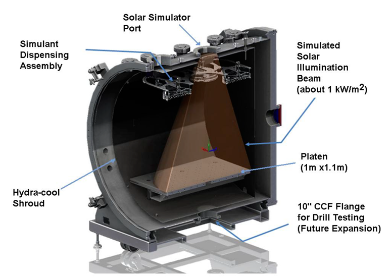
Figure 10: Detail on the DTVAC system interior which highlights features including the simulant dispensing assembly, the solar simulator, and Hydra-cooled shroud. (Ref 1)
Chamber cleaning options for typical contaminants including hydrocarbons
In the event that a vacuum system gets contaminated from traditional intrinsic sources, including back streamed hydrocarbon pump oils, greases, lubricants, cutting fluids and finger prints, there may be a need for a complete disassembly of the system, including every flange, fitting, viewport and feedthrough. The contaminated components can then be subjected to mechanical ablation, vapor degreasing, bake out, and other heroic measures in order to re-achieve true vacuum cleanliness. Chamber cleaning has been well researched and there are several published procedures applicable to TVAC systems. The cleaning procedure for a contaminated DTVAC system may be a little more exotic.
Chamber cleaning options for microbials in 3D substrates
There are strict standards for the amount of organic material, such as amino acids and bacteria, that can be sent into space. Certainly for missions that involve the search for life beyond our earth it is critical that we take no organic contaminants with us – and not bring any forms of extraterrestrial life back home. Traditionally, the autoclave has been the gold standard for sterilization. However, with an operating temperature on the order of 121°C it is not a universally applicable solution. For example, the typical synthetic rubber O-rings used on KF vacuum flanges (with trade names like Buna) are only rated to 100°C. Devices like batteries also do not like to get hot.
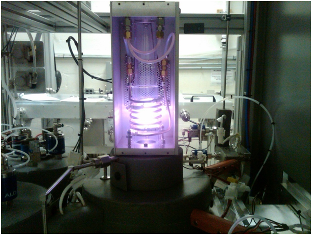
Figure 11: Hydrogen gas plasma in vacuum, Lesker ALD system located at Penn State University.
Presently, there are some low temperature approaches which may be suitable for ridding space craft of microbials. One solution is the use of atmospheric plasma tools which can be used to raster over the various surfaces of the space-bound component – killing all of the biologicals. This does not necessarily remove the dead cellular material from the effected surfaces, so other cleaning steps (see above) may be required.
Another novel approach is the use of low-temperature vacuum enabled hydrogen peroxide sterilization. This approach does not require heat and takes advantage of the sterilization power of hydrogen peroxide and the pervasiveness of gas vapors in vacuum. While it is not clear this has been used in spacecraft it was featured in presentations at the 2017 Contamination, Coatings, Materials, and Planetary Protection workshop hosted by NASA Goddard in July 2017.
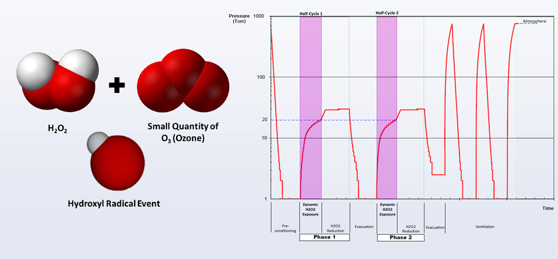
Figure 12: Vacuum and vapor cycle for a low-temperature vacuum-enabled sterilization process (Courtesy TSO3 Corporation)
Containment of contaminants through coatings
Beyond treating surfaces to rid them of contamination, another approach involves functionalization and/or encapsulation. It's widely understood that certain coatings are useful as microbial deterrents. Materials such as silver and titania have demonstrated bug killing capabilities in some applications.
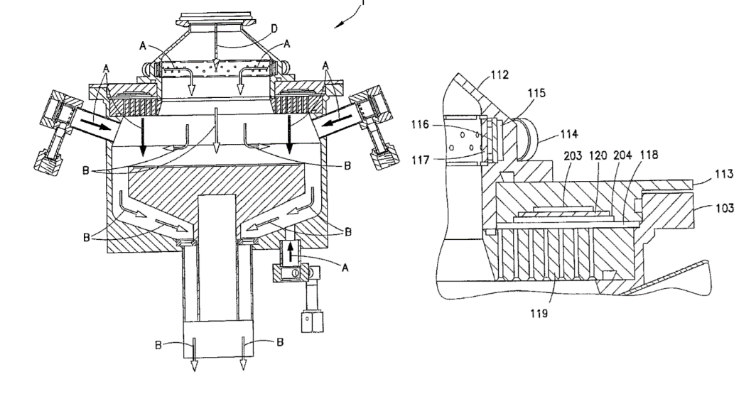
Figure 13: Gas reactor head with flow patterns detailed in arrows. Ref. (2)
Novel thin film fabrication techniques, like atomic layer deposition (ALD) can achieve fully conformal, dense, and well adhered coatings due to the chemical nature of bonds at the substrate interface. Similar to chemical vapor deposition, ALD is a sequential, self-limiting process that has demonstrated excellent step coverage even in trenches with a 40-to-one height-to-width ratio. Coatings deposited by ALD have been used commercially as vapor parries in organic light emitting diodes (OLEDs) and mobile electronics.
Summary recommendations
There are a wide range of prospective contaminants likely to be found in space simulation systems. Some sources, like hydrocarbon pump oil, greases, and lubricants are intrinsic to system design. Other sources, like finger prints, hair, skin cells, and saliva, can be traced to poor vacuum practice by humans. In addition, there can be contaminants from the local environment, like the airborne trace elements and micro-organisms found near the steel mills of Pittsburgh. Vacuum cleanliness is critical to the achievement of low pressures in space simulation systems. It is also critical to the long term sustainability of pristine conditions on the surfaces of components and environments bound for space.
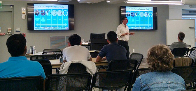
Figure 14: Vacuum technology training at the University of Massachusetts – Lowell campus in April 2017 (Ref KJLC Lesker U Programs)
The recent surge in interest in space travel, whether to build and deploy satellites to service our seemingly unquenchable thirst for connectivity, to provide supply chains to earth orbit systems like the International Space Station, or to expand our species to venues beyond the earth, has brought a large number of new players to the industry. While there exist a variety of solutions for contamination issues for space applications, there is a critical need to train new entrants in proper vacuum system design, vacuum cleanliness, and good vacuum practices. While automation may be able to mitigate some of the human-induced pollutants experienced in TVAC systems, there exists an urgent need for vacuum technology training which is not necessarily available through traditional educational channels.
