Introduction
Sputtering is a relatively mature approach for the deposition of a variety of thin film materials. Initial publications on the process date to the early 1800s (Ref. 1). In its simplest form sputtering provides a route to manufacture high quality reflective coatings for mirrors and potato chip bags; and at the extreme end, for creating the most advanced semiconductor computing devices in the world.
There have been a number of advances in sputtering technology over the last two centuries and continued innovation in this area has enabled ground breaking materials science. Since 1976 there have been more than 45,000 U.S. patents issued on or utilizing sputtering, making it one of the more ubiquitous processes for advanced materials, as coatings and devices.
In all vacuum enabled processes, the capabilities of the tool determine the quality of its output. With more than 24 quintillion molecules in a cc of air (at room temp and sea level), there are plenty of impediments in a vacuum system to impair the quality of a thin film. Recent advances in sputter cathodes (Ref. 2) have enabled further tuning of thin film deposition processes, which improve ease of operation and expand the range of process parameters to deliver higher quality, nanometer level structures.
How sputtering works
Sputtering is a vacuum enabled process designed to create a stream of adatoms from a solid source (the sputtering target) and transfer them across some distance between the source and a substrate (like silicon, glass, or molded plastics) where they will nucleate and form a film with some specific properties, like reflectivity, electrical or ionic resistivity, or a wide range of other properties. Sputtering, and thin film deposition in general, represents an expansive tool set of process parameters that can be optimized to create a wide range of morphologies, grain orientations, grain sizes, densities, etc. It can be used to mate two materials together with pristine interfaces due to the molecular level precision of the sputtering process.
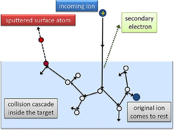
Unlike other physical vapor deposition processes, including thermal or e-beam evaporation, sputtering does not rely on heat to generate a stream of energetic adatoms. Accordingly, reduced process temperatures enable the coating of plastics, organics, glass, and metals. Through the collision with energetic ions portions of the source material, or sputter target are physically knocked out of the solid. Using a process gas such as argon, some small number of molecules are ionized and directed toward the target where they collide with the solid and physically eject some number of adatoms of target material out and toward the substrate (Figure 1).
A user only needs to consult the suite of Structure Zone Models available in the literature, (Ref. 4) to get an appreciation of the effect on material morphology and properties that can be produced through the precisely tuned combination of parameters including pressure, partial pressures, temperature, power level, power delivery, target and substrate biases, on a molecular level.
The effect of base and operating pressures on thin film characteristics
Again, unlike thermal or e-beam evaporation, which can be done at the lowest possible pressure the vacuum system can achieve (i.e., 10-8 Torr), sputtering requires a process gas for the source of ions required to dislodge target material through a series of molecular collisions. While the vacuum chamber of a sputtering system may be capable of pumping to 10-7 Torr, the actual process occurs at a pressure many orders of magnitude higher. The process gas pressure required to strike a plasma is on the order of 10-2 to 10-3 Torr.
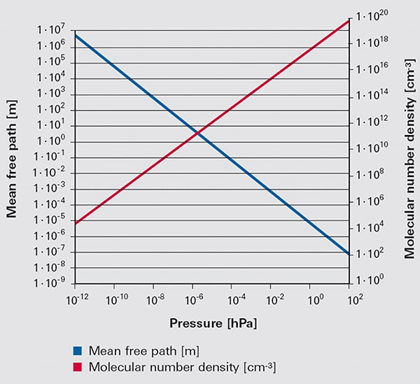
This high pressure burdens the sputter process with relatively short mean free paths between the process gas molecules during deposition. For example, at pressures achievable by a vacuum clean thermal or e-beam evaporation system, on the order of 10-8 Torr, the mean free path between molecules is about 100 meters (Ref. 7). In conventional direct current magnetron sputtering, or dcMS, at 10-3 Torr, the mean free path is only 5 centimeters. Adatoms from evaporation tend to approach a substrate with an incident angle which is normal to the arrival surface. In sputtering, because of the high density of the (inactive) process gas and very short mean free paths, the adatoms arrive at random angles caused by the multitude of collisions that occur in transit to the substrate. The abundance of process gas near the substrate/film interface also enables some of that gas to get absorbed into the growing film causing microstructural defects.
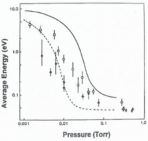
The density and smoothness of thin films can be affected by the energy of arriving adatoms (Figure 2). The more energy they possess the more likely they are to move around on the surface of a substrate and fill in voids in the layered surface. Adatoms arriving with very little energy tend to stick where they land forming irregular islands which are poorly adhered to the substrate. At low pressures, like those achievable in thermal and e-beam evaporation, the initial energy of the adatoms is not large but, because of the long mean free paths the adatoms are not seriously affected by collisions with process gasses as they traverse the throw distance. Conversely, sputtered adatoms have to deal with much smaller mean free paths such that they are doomed to collide with a series of process gas molecules during their journey, giving up energy at every encounter.
Permeation of common gasses through elastomeric seals
Other sources of tramp gasses in any deposition system come from molecules of air, mostly water vapor, desorbing off vacuum chamber walls, sample holders, cathodes, etc... and gasses that enter the system through elastomeric O-rings and gaskets permeable to atmospheric gases including N2, O2, Ar, H2O and CO2. Fortunately, the permeation rate of these gasses through materials like Viton® is well understood so that the contribution of contaminants through elastomer seals can be easily estimated at a given temperature and pressure (Figure 3).
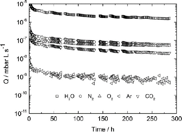
during the pump-down measurement in the case of a saturated Viton gasket. (Ref. 6)
Elastomers are used to seal a variety of entry points into a vacuum chamber including its doors, windows, feedthroughs and sputter cathodes. The accurate calculation of the permeation rate for a system requires a rigorous inventory of the number, diameter and length of all the seals in use.
A permeation rate can be approximated using the following formula (Ref. 8):
Q = K A (P1 - P2) / D
Where:
Q is the permeation rate (cm3/sec)
K is the permeation coefficient (cm3 cm/sec cm2 atm)
A is the area (cm2)
P1 - P2 is the pressure gradient (atm)
D is the thickness (cm)
Notice that the permeation coefficient for a specific gas at a specific temperature must be known as well as the pressure gradient across the seal, its area and thickness.
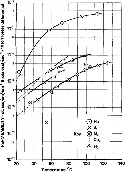
The permeation of the gases that dominate air, at various temperatures, follows, as seen in (Figure 4):
Magnetron sputtering and the effect of cathode design on electron flows
The plasma in sputtering is generated by a large voltage differential between the cathode and anode (of the sputter gun) in the presence of a low pressure gas (typically argon).
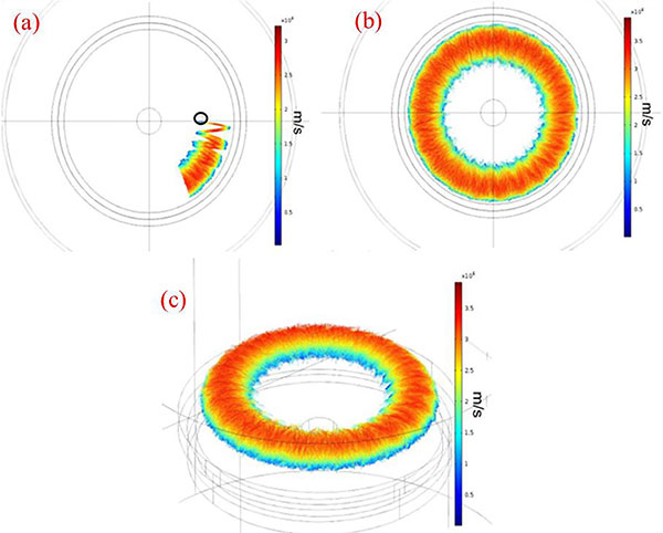
While not mentioned previously, modern sputtering cathodes are almost all outfitted with a system of permanent magnets which help contain the secondary electrons generated by the collision of (argon) ions with the sputter target surface. This swarm of electrons, held close to the surface of the sputter target by the high field of the rare earth permanent magnets, serves to ionize a larger fraction of the (argon) process gas and may, in some cases, actually ionize some of the target adatoms. Priya, Anders and others (Ref. 10) have done excellent work providing detailed images of the movement and speed of the secondary electrons created in magnetron sputtering (Figure 5). It has been shown that they rotate around the race track of a circular target at very high speeds, on the order of 2,600 meters/sec, and their path oscillates between the center and edge fields of the magnet array, as well as up and down from the sheath at the surface of the target to the upper most limits of the magnetic field.
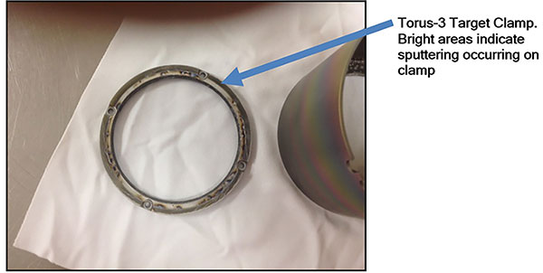
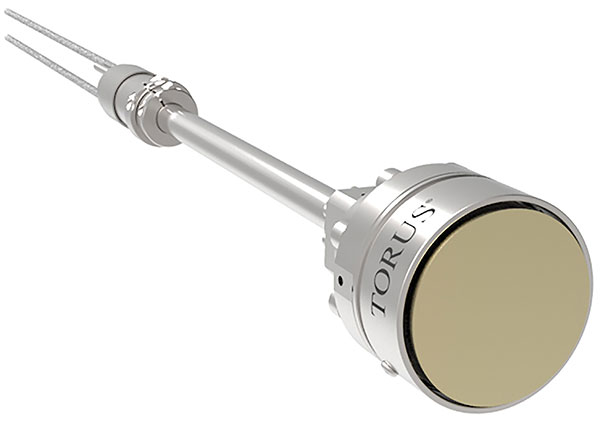
Traditional sputter cathodes, like the TORUS® line from the Kurt J. Lesker Company®, feature a sputter target hold down ring to ensure that the target stays in place regardless of orientation while enhancing the contact with the cathode's target cooling well. The hold down ring, by nature of its approach to clamping, encroaches on the front face of the target and reduces the area available for ionic bombardment. Further, if it does get bombarded it will sputter just like the target material, introducing contamination into the resulting thin films (Figure 7).
In order to mitigate sputtering of the hold down ring cathodes are typically outfitted with a dark space shield. This shield is in close proximity to the target face and serves to block ions from hitting the hold down ring. However, by shielding the ring the target is further shadowed causing a further reduction of ion interaction with the target. Further, the hold down ring and dark space shield are components that typically get coated with a fair fraction of the adatoms generated, further reducing the amount of material that reaches the substrate (Figure 8).

At the extreme the hold down ring and dark space shield can accumulate thick coatings which ultimately flake off and fall into the gap between the anode and cathode - shorting the gun and killing the deposition process.
The dark space shield is also a large and localized sink for electrons so that some of the species that could be used to enhance ionization of the process gas are lost into the shield. This is another detractor from deposition rate and target utilization.
Heat transfer at the cathode/sputter target interface
Unlike thermal and e-beam evaporation which create a stream of energetic adatoms by heating a source material, magnetron sputtering cathodes must be kept cool. The powerful NdFeB magnets in the cathode which provide containment for the flow of secondary electrons have an upper operating temperature of 80°C.
It is estimated (Ref. 11) that 1% of the incident ion energy at the face of the sputter target goes to ejecting target material, 75% goes to heating the target and the balance is dissipated by secondary electrons toward the substrate. Accordingly, the sputter target must be in intimate contact with the cooling well of the cathode. While traditional cathode designs introduce several thermal interfaces between the sputter target and the active component of the cooling system (a water-cooled channel or reservoir), the design featured in this text enables a direct connection to the cooling well, reducing the number of heat transfer interfaces to one. A single interface, perhaps enhanced by the use of thermally conductive vacuum grease, is the most efficient approach to cooling and enables more power to be sent to the sputter target which implies higher deposition rates (Figure 9).
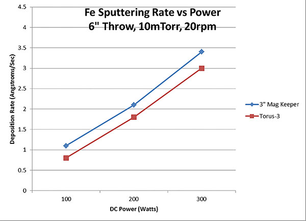
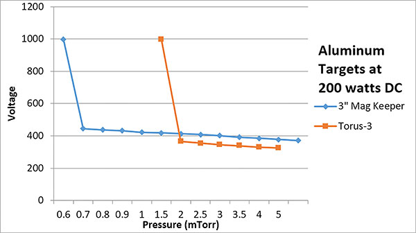
TORUS 3 cathode and a 0.128" Fe target in the Mag Keeper™ cathode. (Ref. 12)
An opportunity to advance sputtering cathode technology
Sputtering, for all of its limitations due to high operating pressures, permeation, shielding, etc... is still a wonderfully flexible deposition process which can produce a wide range of thin film morphologies and properties. Recently, cathode designs have evolved to reduce the impact of some of the tool-specific features on the deposition process and quality of thin films.
Benefits of ultra high vacuum for sputtering
As mentioned, one source of trapped gasses in a vacuum system is permeation through elastomer seals. This systematic contribution to gas load is well understood and can be easily estimated. However, alternative seals, such as ConFlat® Flanges (CF) and some specialized Klein Flanges (KF) outfitted with metal gaskets, either copper for CF or aluminum for KF, can be made to be gas tight, or hermetic. These gas tight seals prevent permeation and ALSO allow the chamber to be pumped into the ultra-high vacuum pressure range (< 10-8 Torr) and enable system baking. In general, it is not possible to get a chamber lower in pressure than about 10-8 Torr without baking. All elastomer seals have relatively low resistance to temperature so that baking is limited to about 150°C or less. Metal seals more than double the temperature range for system bake-out up to 350°C - 450°C. At these temperatures (for 100 hours or so) a substantial amount of adsorbed gasses can be pumped away from interior surfaces and ultra high vacuum can be achieved.
Path to an optimized sputtering cathode
Several years ago, engineers at the Kurt J. Lesker Company began work to develop a sputter cathode that could exceed the traditional performance of the classic magnetron design. The motivation of the development was to improve several characteristics of the cathode to make it more user friendly, but in the course of their work their developments resulted in improved features like deposition pressure, deposition rate and arriving adatom energies.
Reduction of components which shield
As mentioned, several of the components in a traditional magnetron are both shields for ions while providing unproductive surfaces near the target which accumulate harmful coatings. A fix for the function of the hold down ring has been to utilize the pull of the cathode's integrated magnet pack to anchor the sputter target in place. A small disc of magnetic material is attached to the sputter target or sputter target backing plate and its attraction to the cathode's center magnetic holds the assembly in place. The pull is also ample enough to create a sufficient thermal interface with the cathode's cooling system.
With the hold down mechanism safely located behind the target out of the path of any incoming ions, the dark space shield is no longer need. Accordingly, it has been dropped back behind the plane of the sputter target exposing more target material to a swarm of ions. Further, with the dark space shield substantially removed from the containment field created by the cathode's magnet pack, fewer ions are depleted near the target's surface. The combined effect of eliminating the hold down ring and dark space shield results in an increased deposition rate (Figure 10).
User friendliness is also enhanced by reducing the amount of time spent removing unwanted film deposits on the shielding and reduced down time due to shorts caused by material flaking into the gaps between the anode and cathode. Target changes are also simplified with the elimination of the disassembly procedure for the dark space shield and hold down ring. The target can simply be pried away from the surface of the cathode with a gloved hand and a specialized non-magnetic, tool.
components that shield the target has increased the accessible target surface by 30%.
Lower the process pressure
The increase in the target surface area available for ionic interactions and the reduction in the number of ions lost to shielding enables the cathode to be operated at lower pressures. In tests run against a traditional magnetron cathode with a target hold down ring and dark space shield, demonstrated a reduction in the lowest achievable operating pressure by a factor of two.
The reduction in background pressure increases the mean free path to about one meter, which is much larger than the throw distance in most deposition systems. (Ref. 11) (Ref. 7). This increase in mean free path substantially reduces the number of collisions and lost energy for adatoms in transit to the substrate. More energy in the final adatom collision means that the constituents in the forming film will have more mobility and be able to form dense, better adhered, and smoother coatings (Figure 12).
Improved process environment control
As mentioned, sputtering is highly sensitive to the background gas pressure in the chamber and the species of gasses that contribute to that pressure. One source of unwanted gases in a vacuum system is permeation through elastomer seals. Permeation can be eliminated by graduating to metal seals, either copper or aluminum. In order to eliminate the possibility of gas loading through the sputter cathode the enhanced cathode has completely eliminated elastomer seals. The head of the gun which faces the vacuum space is hermetically sealed from the atmosphere side of the cathode with a CF styled flange assembly. The copper metal gasket in the cathode is impervious to permeation, eliminating one source of contamination.
True ultra high vacuum base pressure
The elimination of elastomer seals in the cathode, coupled with the use of CF flanges throughout the deposition system, enables the vacuum chamber to be baked. The copper sealed CF flange can be baked to 450°C if the gasket is protected from oxidation with a coating of Ag or Ni. However, much of the rest of the real estate in a thin film deposition system cannot tolerate that thermal excursion. Looking at the literature for commercially available NdFeB magnets, the upper operating temperature is on the order of 120°C. While that is not as good as a 200°C bake it is 1,000 times better than pumping a chamber at room temperature for an extended period. While the ultimate working pressure of the system may be on the order of 10-3 Torr, the achievement of ultra high vacuum in the system prior to the start of deposition will eliminate many of the gases resident in a chamber only pumped to high vacuum (10-6 Torr) that can cause defects in thin films.
Film defects can include the inclusion of unwanted gases from the process and chamber into the otherwise desired microstructure. Inclusions can create stress in films - which may be bad, or can in some instances be used to achieve unique properties. Irregular grain growth, whatever the cause, may induce some level of shadowing (where some functional sites on a growing film are shielded by odd grain formations), which creates low density films.
Summary
Sputtering is a magnificent materials fabrication process. It is, however, hindered by some basic vacuum system realities. Advances in tool designs which continue to expand the range of process parameters supported by a sputter cathode help advance robust global research in thin films. In this paper an approach was described which helps broaden process possibilities which may make possible more pristine thin films with a minimum of user supplied maintenance.
References:
- Greene, et al... , Review Article: Tracing the recorded history of thin-film sputter deposition: From the 1800s to 2017, Journal of Vacuum Science & Technology A 35, 05C204 (2017); doi: 10.1116/1.4998940
- The Kurt J. Lesker Company, Jefferson Hills, PA 15025, "Hermetically Sealed Magnetic Keeper Cathode", Patent No.: US 10,115,574 B2, October 30, 2018.
- A Anders, Tutorial: Reactive high power impulse magnetron sputtering (R-HiPIMS), Citation: Journal of Applied Physics 121, 171101 (2017); doi: 10.1063/1.4978350, View online: https://doi.org/10.1063/1.4978350, View Table of Contents: http://aip.scitation.org/toc/jap/121/17
- J. A. Thornton, The microstructure of sputter deposited coatings, Citation: J. Vac. Sci. Technol. A 4, 3059 (1986); doi: 10.1116/1.573628, View online: http://dx.doi.org/10.1116/1.573628, View Table of Contents: http://avspublications.org/resource/1/JVTAD6/v4/i6, Published by the AVS: Science & Technology of Materials, Interfaces, and Processing (for other references please contact the author at jrg@lesker.com)
- Lieberman, Michael A.; Lichtenberg, Allan J. (2005). Principles of plasma discharges and materials processing (2nd ed.). Hoboken, N.J.: Wiley-Interscience. 546. ISBN 978-0471005773. OCLC 59760348.
- Makfir Sefa, and Janez Setina, Comparison of permeation of atmospheric gases through Viton O-ring gaskets for different initial conditions, Journal of Vacuum Science & Technology A 35, 041603 (2017); doi: 10.1116/1.4984292
- Ref: https://www.pfeiffer-vacuum.com/en/know-how/introduction-to-vacuum-technology/fundamentals/mean-free-path/
- Ref: https://www.marcorubber.com/o-ring-permeation.htm
- L. Laurenson, and N. T. M. Dennis, Permeability of common elastomers for gases over a range of temperatures, Journal of Vacuum Science & Technology A 3, 1707 (1985); doi: 10.1116/1.573005
- Priya Raman, Magnetic field optimization for high power impulse magnetron sputtering, Dissertation, 2016, University of Illinois at Urbana-Champaign
- L. T. Ball, I. S. Falconer, D. R. McKenzie and J. M. Smelt, Sputtered Copper, J. Appl. Phys 59, 720 (1986)
- R. Belan, Kurt J. Lesker Company, Comparative Performance Testing of the 3" Mag Keeper and the TORUS 3HV Sputtering Guns, Internal R&D Lab Report
- Edited by John L. Vossen & Werner Kern, Thin Film Processes, Academic Press, copyright 1978.
