Introduction
With the dramatic growth expected in many industries which require high temperature vacuum systems such as space simulation systems, 3D printing of metal components, the manufacture of single crystals for the LED and semiconductors and others, alternatives to traditional water cooling approaches may offer performance gains coupled with reduced costs. Temperature control for these applications can take several forms. In the case of space simulation, the vacuum system is designed to duplicate the temperature (and pressure) extremes that will be experienced by satellites in earth orbit, or beyond, which may require rapid cycling from -130°C to +130°C. For crystal growing, using methods such as the Kyropoulos process, where a crystal is 'pulled' from a melt of material, such as silicon, the internal temperature of a vacuum system may reach +1,450°C. In one case, the temperature control system for the vacuum chamber is designed to provide a user-specified profile of cold-to-hot and in another the system is required to safely mitigate and protect the system from the extreme temperature required to liquify silicon.
Traditional approaches to cooling vacuum systems have relied on various conventional structures, such as tubing and C-channels, being soldered or welded onto the outside of the vessel. In applications with extreme heat loads, where the heat exchange rate between discrete channels and the chamber is insufficient, double walled chambers have been utilized which enable an extreme flood of coolant to the chamber walls. These approaches have significant technical and cost limitations.
Cooling methods that utilize a weld to form the seal can also suffer from a type of corrosion called crevice corrosion. If a small crevice remains where the weld seals the trace to the chamber wall, a drop in pH and a potential drop across the crevice can result in an attack on the oxide layer of stainless steel and start corrosion within the wall of the chamber.
Copper tubing on chamber walls
The simplest approach to temperature control for vacuum chambers involve soldering copper tubing to the outside of the system and does not suffer from crevice corrosion. This practice dates back to the very early days of vacuum technology and can still be seen in the design of diffusion pumps. See Fig 1.
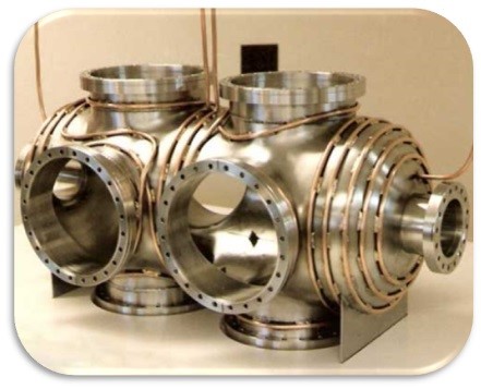
Figure 1
This approach suffers from the minimal interface area available from a tangential joint between a tube and a flat surface. In addition, in the experience of this author, the loss of fluid flow during processing, due to a power or pump failure, can cause the chamber to overheat, melting the solder and creating a catastrophic failure.
Welded or Soldered C-Channel
The C-channel approach bests tubular cooling channels in the increased surface area of the interface with the vacuum vessel. Welds also can withstand substantially more heat that solders avoiding the issues of the above method. However, fluids are none too keen to flow around tight 90° turns such that the angular channels typical employed in C-channel pathways result in dead zones, pressure drops, and chaotic flows. See Fig 2.
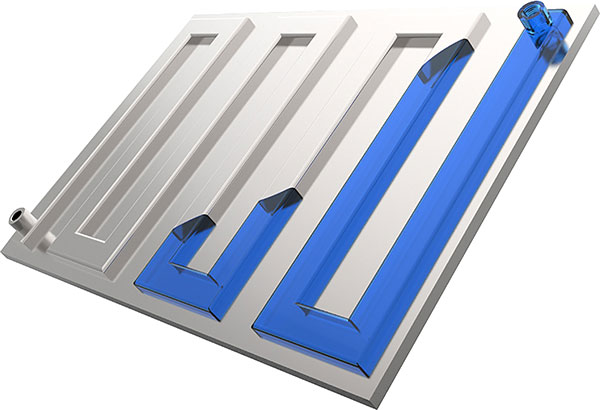
Figure 2
There is also a physical limit on how close together the trace can be, as the weld torch gets obstructed by the previous loop of the trace. This can also make it hard to configure this around ports on chambers.
This method is particularly susceptible to crevice corrosion. If this is coupled with a higher heat area in a low flow area, corrosion can be rapid and lead to failure.
Channels Machined into Chamber Walls
Another traditional approach involves machining a channel for fluid flow into the chamber walls and then capping that channel with plate. See Fig 3.
While this approach may be straightforward with respect to the machining and welding, it does require that the thickness of the chamber walls be increased to compensate for the likelihood of preferential bowing at the channels due to the pressure differential between the atmosphere and vacuum side of the system. Bowing of the chamber walls under vacuum can cause a variety of failure modes including the disruption of sealing surfaces, the miss-alignment of critical components and the eventual cracking of the fluid flow channels.

Figure 3
This approach also has a higher cost than most other types, but it does have the advantage that the cooling trace can be close to the inner wall of the chamber and the surface area in contact with the coolant is much higher. This makes it suitable for the very highest heat load applications, but it is usually not cost effective for lower heat load applications.
It can still be susceptible to crevice corrosion, though in the author's experience, it is much less so than welded on C-Channel.
Double walled vacuum chambers
This approach allows for the maximum possible fluid flow through the temperature control system but with a substantial bump in manufacturing difficulty and costs. This approach essentially doubles the material requirement of the system and there are challenges in matching the inner and outer jackets with baffles to direct flow in such a way as to eliminate short circuits in the water path. It may still be subject to the same problems with dead zones, chaotic flow and crevice corrosion found in C-channel based approaches. See Fig 4.
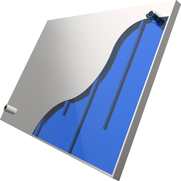
Figure 4
Pillow Plate Cooling
Pillow plate cooling is formed by having a thinner outer skin welded onto a thicker inner skin. These are then sealed around the edges and spot welds are put in place at regular intervals.
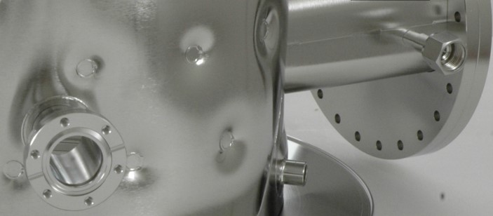
Figure 5
This is then inflated with high pressure water to form a void. This has the benefit that a very high surface area of the chamber wall is cooled with minimal pressure drop. It does however, rely on chaotic flow around the spot welds and can still result in low flow areas. See Fig 5.
An alternative approach to fluid flows
An approach has been developed by the Kurt J Lesker Company® that combines the fluid flow dynamics of a radiused system with the ease of manufacturing a C-channel based system. Hydra~Cool™ is a process that enables a highly configurable channel trace combined with superior surface area coverage, improved corrosion resistance, improved fluid flow, minimized fluid volume and protrusion into the atmosphere side of the vacuum system.
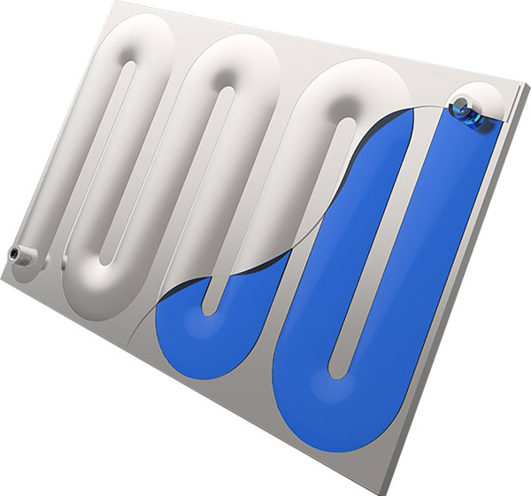
Figure 6
This is manufactured in a similar way to the pillow plate, but instead of using spot welds, a precise path can be engineered to give an optimized flow around a chamber.
For more an in-depth study of fluid flow in radius-based systems refer to: http://nvlpubs.nist.gov/nistpubs/jres/21/jresv21n1p1_A1b.pdf
Other water trace designs, with angular geometries, are prone to the establishment of dead zones or low flow regions, which will promote corrosion in steel-based cooling systems. The radiused channels enabled by the Hydra~Cool approach deliver reduced resistance to fluid flow which increases the probability of high throughput of the cooling media.
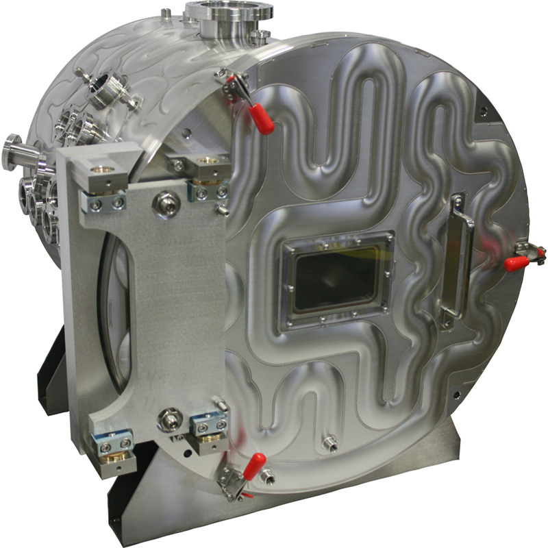
Figure 7
The high surface area, serpentine-style, water channels possible with the Hydra~Cool approach also reduce the amount of fluid flow required, compared to traditional approaches such as soldered tubular or welded C-channel structures, which substantially reduces the energy demands, based on pump-driven circulation systems. The improved contact area with the hot surface combined with the reduced resistance to flow, enables a reduced flow rate to achieve substantially improved heat transfer.
The experimental setup shown in figures 8 & 9 used heaters on the underside of the test panel. The panel was set on 1.2mm sheet metal side walls to create a pseudo-oven. Thermocouples are set up on the inside of the oven and on the surface of the panel. The inside was kept at atmospheric pressure – not vacuum, so thermal transfer was increased by conduction and convection as well as radiative heat.
Figure 8 shows the test piece with no water flow, demonstrating an external surface temperature of 150°C.
Figure 9 shows the test piece with a water flow of 4 l/m, achieving an average surface temperature of 25°C.
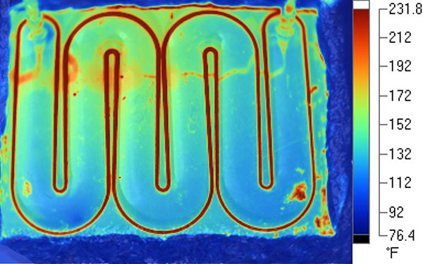
Figure 8
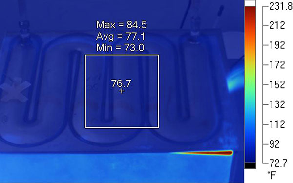
Figure 9
The Hydra~Cool approach also offers a reduced footprint and trace height with respect to that typically required for traditional water trace approaches. The nominal channel height of 5mm is substantially less than other approaches.
Summary
Traditional chamber cooling approaches have several drawbacks. An alternative approach based on serpentine, radius-based, welded onto the surface of a chamber offers improved heat transfer with lower probability of dead zones, reduced corrosion resistance and better pumping efficiencies. Demonstrated success in applications such as e-beam deposition, crystal growth and space simulation will lead to the extension of the Hydra~Cool approach to other applications.
