Introduction & Bibliography
We examine methods of manufacturing thin film and deposition sources in Vacuum Systems. Here, we give a brief introduction to the mechanics and physics of sputtering and thermal evaporation sources.
For those interested in greater detail, the book list below gives a good cross section of the information. The subject matter is so huge there is little content overlap between these books. Also, despite their age, the first two remain frequently quoted references. (Given the short publication lifespan of technical books, do not expect to find many "in print").
- Handbook of Thin Film Technology, Maissel & Glang, McGraw Hill 1970, Lib. of Congress Card No. 73-79497
- Thin Film Processes, Vossen & Kern, Academic Press, Inc. 1978, ISBN 0-12-728250-5
- Thin Film Processes 2, Vossen & Kern, Academic Press, Inc. 1991, ISBN 0-12-728251-3
- Handbook of Sputter Deposition Technology, Wasa & Hayakawa, Noyes Publications 1992, ISBN 0-8155-1280-5
- The Materials Science of Thin Films, Ohring, Academic Press 1992, ISBN 0-12-524990-X
- Thin-Film Deposition'Principles & Practice, Smith, McGraw Hill 1995, ISBN 0-07-058502-4
- Handbook of Thin Film Process Technology, ed. Glocker et. al., Institute of Physics Publishing 1995 ISBN 0-7507-0311-5
- Physical Vapor Deposition of Thin Films, Mahan, Wiley Interscience 2000, ISBN 0-471-33001-9
- Sputter Deposition, Westwood, AVS 2003
Sputtering
What Is Sputtering?
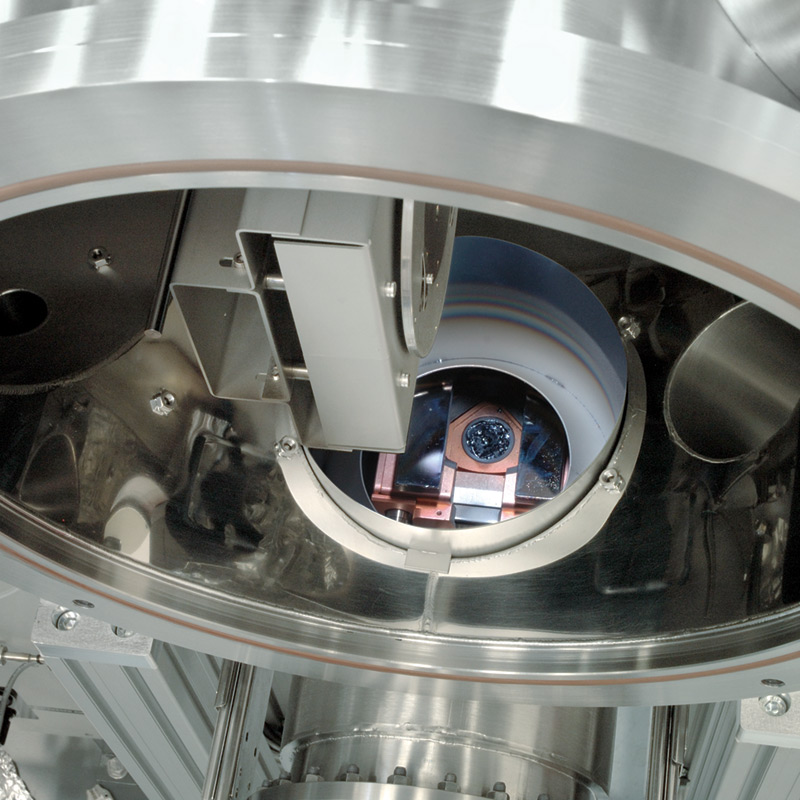
Sputter deposition, commonly called sputtering, removes atoms/molecules from a solid target's surface, projecting them into the gas phase from which they condense on another surface. In the simplest arrangement, a high voltage is applied between two circular, plane-parallel disks: a target (cathode) and a substrate (anode) mounted a few inches apart. An inert process gas at 1 to 100 mTorr flows between the electrodes. Initial electrons from the target's surface cause cascade ionization in the gas, forming a plasma loosely defined as a confined region with equal concentrations of electrons and positive ions.
Because the plasma is both electrically neutral and highly conductive, there is little voltage drop across it. The drop occurs across thin "dark space" regions between the plasma and each electrode. The target's negative potential attracts positive ions from the plasma's edge. They hit the target with sufficient kinetic energies to eject neutral target atoms/molecules by energy transfer.
While traveling from target to substrate, each ejected atom hits numerous gas atoms/molecules that deflect them and cause energy loss. By optimizing the target-substrate distance, the atoms approach the substrate's surface from partially randomized directions, producing a reasonably uniform film thickness across a textured substrate's surface.
For circular sources, the optimum throw distance between target and substrate is larger than the target's diameter to "smooth out" the source's ring-like deposition pattern. By contrast, a linear production source used to coat large area substrates moving across it, has a short optimum throw distance. Here the linear source's end-effects disturb the uniformity.
Sputter Sources
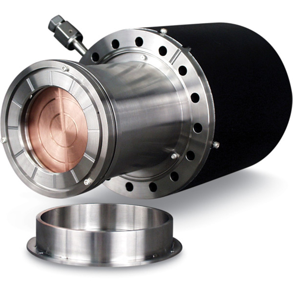
The differences between diode, magnetron, balanced/unbalanced, RF/DC power options, etc. for various sputter sources are discussed in Vacuum Systems.
A source's vacuum compatibility depends on its specific design, but all are suitable for 10-6 Torr to 10-7 Torr range. Some true UHV versions are compatible with 10-10 Torr and bakeable to 400° C (with magnets removed from the air side). The latter group is used where the process chamber must reach UHV conditions (for cleanliness) before backfilling with process gas.
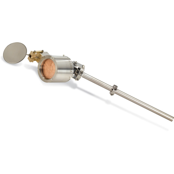
In R & D applications, sources are often mated to existing chambers and the relative positions of the source's mounting port and the substrate holder determine which source mounting is most appropriate: (i) The axial source has its target's surface perpendicular to its utilities tube; (ii) The right angle has its target's surface parallel to the utilities tube; and (iii) The flex has the source and tube connected by a flex metal hose, enabling the angle between their centerlines to vary from 0° to 45°.
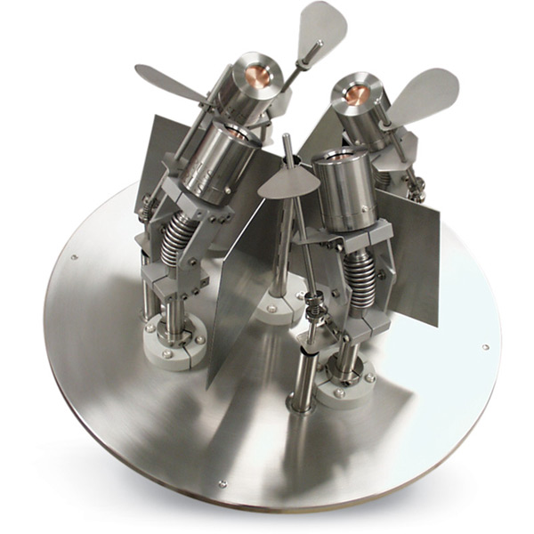
An additional consideration for R & D applications is varying the film composition. For simultaneous or sequential deposition of different materials and quick changes in film compositions, a cluster of 3 or 4 sputter sources mounted on one flange with integral cross-contamination shields, shutters, and gas feeds, may be an ideal arrangement.
That implies thicker targets which, in turn, demand correctly shaped magnetic fields to penetrate those targets. Another common production need is depositing films on large rectangular substrates. This is addressed with linear sputter source (longer than the substrate is wide) and then moving the substrate across the source during sputtering.
Sputter Targets
Most of the electrical energy entering the plasma converts to thermal energy in the target. Water flows through the source and cools the target by direct or indirect cooling. In direct cooling, the target's non-vacuum side has water flowing over it. Obviously, the target: (a) must be thick enough to ensure sputter etching does not compromise vacuum integrity and (b) must not react with water. For these reasons, direct cooling is often used in high volume production sources where thick, unreactive targets are common. For indirect cooling, water cools the non-vacuum side of the source's cooling well-a copper 'cup' into which the target is clamped. Indirect cooling is used for low-volume production and R & D sputter sources. Indirectly cooled targets are not bonded to their cooling wells because that would make replacement difficult. However, poor thermal contact between cooling well and target is the cause of significant problems. Poor heat transfer, particularly noticeable when low thermal conductivity targets (oxides, nitrides, glasses, ceramics, etc.) are sputtered leads to: (a) thermal expansion stress cracks in the target; or (b) melting of the indium bonding target to its backing plate.
Two approaches are used to reduce the incidence of these problems: (a) a thermally conductive polymer sheet or silver impregnated paste is placed between target and cooling well; and (b) power is applied or shut off in a series of slow "ramps-and-soaks." In practice, this means the power is slowly ramped from zero to, say, 20% of the full, desired sputter power. The target is then allowed to soak at that power for some minutes before another ramp is initiated. Increasing or decreasing power in this way is good practice for both sputtering and evaporation applications.
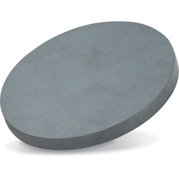
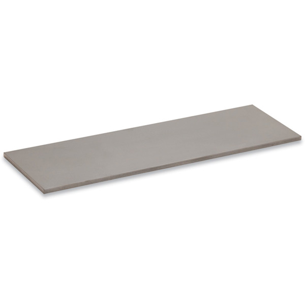
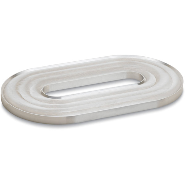
Targets are appropriately shaped to fit their respective sources and a wide variety of circular, linear, cylindrical, wedge-shaped, race-track, truncated cones, and other forms are used.
Sputtering Strengths
- The depositing atoms/molecule's kinetic energy is usually a few eV, giving good film adhesion on appropriate substrates.
- Sputtering does not require melting.
- Materials rarely 'spit' lumps at the substrate.
- The source can be mounted in any orientation.
- Although plasma electrons are "hot," other species are not and there is little radiative heat transfer to substrates.
- Surface coverage is not strictly line-of-sight.
- Elemental mixtures, alloys, and some chemical compounds can be sputtered without changes in stoichiometry.
- Reactive sputtering (O2 or N2 added to Ar) has many applications. In particular, it avoids the problems associated with sputtering low thermal conductivity targets.
- Linear sources coat large area substrates with metals and inorganic materials.
Evaporation
What Is Evaporation?
As noted in the Systems, strictly, evaporation is the conversion of liquid to vapor while sublimation is the conversion of solid to vapor. But following common practice, both processes are called evaporation here.
Evaporation Sources
Various evaporation sources are described in the Technical Notes for the Section 9 and Section 15. Here, sources not noted in those sections are described together with source combinations used for simultaneous or sequential deposition.
Thermal Sources: As pointed out in Section 15 Technical Notes, alloys and mixtures rarely give films with the original material's stoichiometry. To deposit alloys successfully requires simultaneous deposition from a number of thermal sources in close proximity. Multiple sources can be mounted on one flange in a cluster.
Effusion Cells: The evaporation temperatures of organic materials are low, typically much less than 500° C, and the evaporation rate is exceptionally sensitive to the material's temperature. To achieve satisfactory film deposition demands rigorous temperature control. Low temperature effusion cells, designed specifically for depositing organic thin films, are frequently used in co-deposition and sequential deposition applications. Combinations, some with as many as 10 sources mounted on a single flange, have been developed to fill this need.
E-Beam Sources: Physical size alone makes the installation of more than two e-beam sources in a chamber unlikely. However, multi-pocket sources can be used for sequential evaporations and one e-beam source with multiple thermal sources is a common configuration for simultaneous or sequential deposition.
Linear Evaporation Sources: The continuing emphasis on optically active and electrically conductive organic materials for display panel technology revealed a need for a source capable of covering large substrate areas with highly uniform coating. Our (patented) linear source coats substrates up to 600mm wide of any length. Because this source's footprint is only 3" wide, multiple sources can be mounted side-by-side in an in-line system for sequential deposition of organic materials.
Evaporation Strengths
- Thermal evaporation equipment costs are usually low.
- Mechanical arrangements are often simple and constraints few.
- Material usage is high and re-filling is simple. (For RF induction sources it is automatic during operation.)
- E-beam and RF inductive evaporators give high deposition rates.
- For R & D applications, thermal evaporation is particularly flexible.
- Organic materials can only be deposited by evaporation.
- Linear sources coat large area substrates with organics and high vapor pressure inorganic materials.
Ion Bombardment
What Is Ion Bombardment?
Ion bombardment is used in three ways for surface modification and thin film deposition:
Substrate Cleaning. Using high-energy inert gas ions, bombarding the substrate provides a good way of removing tightly adsorbed gases and vapors. It is frequently used just prior to deposition.
Surface Modification. For some substrates, particularly plastics, ion bombardment is used to "modify" the surface. This means not only are adhering atoms/molecules removed as in substrate cleaning, but the surface morphology is changed in a way that increases the adhesion of any film that is immediately deposited on it.
Morphological Effects. A thin film deposited by any PVD or CVD method may have a film morphology that: is columnar, grainy, with many voids, and has a lower density than the bulk crystalline material. To "densify" the film, it is bombarded with inert gas ions during deposition called ion-assisted deposition. When sputtering, an unbalanced source can provide some degree of substrate ion bombardment and for CVD methods, the "plasma enhanced" versions create similar bombardment conditions. However, where the technique cannot be adapted to provide that bombardment, separate ion sources are used.
Sputtering & Evaporation Applications
This is a small selection of the total number of products made by physical vapor deposition methods, roughly grouped according to the main body of users.
- IR-reflective architectural glass
- Anti-reflective lenses for laser lenses
- Band-pass and notch filters, superlattices, rugates
- Hardcoats for printheads, machine tools, turbine blades
- Anti-corrosive coats for nuclear fuel rods, marine components, jet engine turbine blades
- Impermeable coatings for food packaging film, moisture barriers
- Photovoltaic devices, solar panels
- Organic flat-panel displays
- Optical/conductive flat-panel coatings
Consumer
- Reflective/magnetic video disks, compact disks, space blankets
- Decorative bright-plastic parts, car "chrome," jewelry, plumbing fixtures
- All mirrors, mirrored sunglasses
- Anti-reflective camera lens coatings
- Magnetic disk drives, disk read heads
- Metal film capacitors and resistors,
- IC metals, resistors, insulators, gate barriers
- ICs for all industrial, business, military, and consumer computers
- Microprocessors for consumer electronics
- Optical data storage disks
Medical
- Wearcoats for prosthetic joints
- Culture-surface modification for bacteria growth
- Neutralizing of passivating catheters
- Super-insulation for cryogenic magnets in diagnostic scanners
Scientific
- Heat-resistant coating of SEM samples
- High-Tc superconductors
- Tribology films
- Telescope mirrors
Military
- Conductive layers for aircraft canopies
- IR-transmissive optics
- Light-amplifying night vision optics
- Anti-damage coating for laser windows
Ion Sources
An ion source, in this context, directs a wide, uniform flux of ions toward the depositing film. The energy is chosen so the incident ion exchanges energy with the film's atoms, causing the latter to move without sputtering.
Some ion sources use thermionic emission of electrons to generate ions. However, this limits their use to inert gases, and they may be adversely affected by reactive species from the chamber.
Other ion sources have no filaments and will make ions of both inert and reactive gases. This is particularly useful where surface modifications require oxide or nitride formation.
Contact us by clicking here to discuss your specific vacuum application and process equipment needs.
