Products of Thin Films
A few examples of products that would not exist, or be as effective, without vacuum thin film PVD and CVD deposition processes.
Consumer: CDs and DVDs; aluminized plastic food packaging; camera lenses; mirrors; optical coatings for windows, glasses, and sunglasses
Commerce: Computer hard-drives and GMR read heads; headlamp reflectors; architectural glass; tool hard-coatings; diamond-like films; semiconductor chip production; organic electronics and displays; transparent conducting layers; magnetic memory; advanced solar panels; MEMS accelerometers
Military: Aircraft canopies; night vision goggles; FLIR vision devices
Medical: Eximer lasers for eye surgery; passivated prosthetic joints; coated stints; super-insulation for MRI magnets
Research: Neutron beam guides; laser mirrors; optical filters; super-lattices; rugates; high/low Tc superconductors; SQUID magnetic detectors; quantum dots
CVD & PVD
Two major in-vacuum processes are CVD and PVD (described in Section 15, Vacuum Systems). The list of products using a CVD/PVD step to make a thin film is both exceptionally large and diverse and includes all IC products made by the semiconductor industry, computer hard disk drives and their read-heads, anti-reflective coatings on camera lenses and reflective coatings on architectural glass, aluminized plastic films used in food packaging and thermal insulation in superconducting magnets, "mirror" sunglasses, hard coatings on machine tools, body-fluid compatible materials on prosthetic joints, OLED displays, aircraft canopies, and car rear-view mirrors and headlamp reflectors.
Often a chamber is evacuated to low pressure to ensure "clean" initial conditions for some product-making process. Process instrumentation is used here to cover ancillary equipment that monitors or controls the process's progress or the supply of some essential "utility."
Controlling Gas Flows
All CVD and many PVD processes require a gas or vapor flowing through the chamber at a relatively low pressure and controlled rate. A few examples are (a) sputter deposition that requires a constant flow of pure Ar at a fixed low pressure; (b) reactive thermal evaporation, which needs a reactive gas (O2 or N2) to form the final product; (c) dry etching that may use a single gas (Ar, O2, CF4) or a mixture; and (d) CVD depositions using vapors and separately supplied gases (tetraethoxysilane + O2 to produce SiO2 films).
Thin Film Growth
Among the many factors that affect thin films made by PVD methods, the material's deposition rate and the film's final thickness are often critical. The deposition rate can affect morphology and the film's thickness determines its electrical, optical, and mechanical functioning. Quartz crystal thickness monitors are frequently chosen to determine film growth rate and instantaneous thickness in PVD processes.
Power Supplies
Most vacuum processes require electrical power as a utility inside the vacuum chamber. Examples from thin film processes might be: (a) evaporating a material; (b) raising a substrate's temperature so that a particular CVD reaction works; (c) heating a substrate to manipulate a film's morphology during a PVD process; and (d) sputtering. The various types of power supplies required for these processes are discussed later.
Mass Flow Controllers & Meters
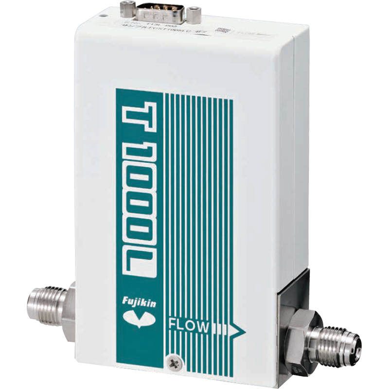
The name describes the function-mass flow controllers (MFCs) control (or for "meters," measure) the flow rate of gas passing through them. More specifically, they control the mass flow in units of pressure x volume/unit time. They do not control the volumetric flow in units of volume/unit time. The distinction is important. Mass flow rate is actually the number of molecules passing through the device per second. For a stated volumetric flow rate, the number of molecules passing through the device might be 105 or 1025 per second... it all depends on the pressure. Clearly, when considering chemical or physical processes, the critical parameter is more likely to be the number of molecules available per unit time than the volume they occupy.
To lower equipment costs, leak valves are sometimes chosen to control gas flow. But as explained in Valves, this is not really flow control. The flow rate through a leak valve depends on the specific gas, up-stream pressure, down-stream pressure, and ambient temperature. Within a very wide range of working conditions, MFCs are unaffected by these factors.
Permanent Gases
Any gas that cannot be converted to a liquid by increasing the pressure at room temperature(20° C) is called a permanent gas. Examples are N2, O2, Ar, He, H2, NH3, CO, F2, CH4, etc. To measure the mass flow of a permanent gas, a known fraction of the total gas flow is automatically diverted into a laminar flow sensing tube inside the MFC. The tube may have two or three sensors wrapped around it (at entrance, exit, and mid-point) and an overall heater. Knowing the thermal characteristics of the specific gas and the temperatures at two or three sensor locations, an (gas-specific) algorithm is used to calculate the mass flow in the sensing tube, and from that, the total flow. The sensing tube's exit flow is re-mixed with the main flow and (in the controller version) passes through a solenoid valve that responds to feedback from the flow measurement circuit. The accuracy of flow control is ±1% of the full scale reading (with all error sources taken into account) with repeatability at ±0.2% full scale.
Vapors
Vapors and Temperature
With a particularly low vapor pressure (VP) material, like TEOS (VP 2 Torr at 25°C), the bulk material's temperature must be raised so the VP is at least high enough to support the required flow rate. The bulk temperature for TEOS, for example, might need to be 70°C, which will give a VP of ~24 Torr.
Obviously, all tubing from the bulk material's container to the MFC and the MFC itself must be maintained at a temperature well above 70°C to prevent TEOS condensing to liquid. Since mass flow measurement methods are temperature sensitive, it is important that the MFC is maintained at a constant higher temperature.
What is needed after the MFC depends on its outlet pressure. For TEOS, if the pressure is considerably less than 2 Torr, then the tubing after the MFC does not need to be heated, although it may still be prudent. But if the pressure exceeds 2 Torr, or even approaches it, then the tubing from MFC to chamber and chamber itself must be heated above 25°C to avoid condensation.
As used here, vapor is the gaseous phase of a chemical that also exists as liquid or solid at, or near, normal temperatures and pressures. As an example from everyday experience, the atmosphere always contains water vapor. Reducing the air's temperature causes water vapor to change to liquid water—as in cloud formation or fogging of bathroom mirrors. One example of vapor-solid transitions is iodine crystals. At room temperature, iodine's vapor pressure (VP) is ~0.4 torr. Cool a trapped I2 vapor volume to 0° C and the VP drops to 0.05 torr—the vapor condensing as solid iodine.
In practical vacuum processes used in the semiconductor industry, vapors such as: tetraethoxysilane (TEOS), VP ~2 Torr at 25°C; titanium tetrachloride (TiCl4), VP ~10 Torr at 20°C; and hexamethyldisiloxane (HMDSO), VP 55 Torr at 30°C, are commonly used. To measure the mass flow of these vapors, two factors must be addressed: (a) the MFC must handle the vapor without causing reaction or decomposition; and (b) the temperature of the tubes/ valves containing the vapor must be above the temperature at which condensation will occur (see Vapors and Temperature sidebar).
Unlike gases, vapor flows cannot be measured or controlled using MFCs that work on the principles described in "Permanent Gases." The pressure differential used in gas MFCs are not available from most vapor sources and gas MFCs may have elastomer/polymer seals that may be incompatible with the vapors. A vapor MFC's design centers around (a) all metal surfaces in contact with the vapor, (b) a constant body temperature well in excess of 25°C, and (c) using a flow measurement method that works at low inlet pressures and, therefore, low pressure differential.
The first measurement method uses choked flow. If a vapor or gas flowing through an orifice (or short pipe) is in viscous flow and has an upstream pressure roughly twice its downstream pressure, the orifice goes into choked flow. The mass flow through the orifice depends only on the upstream pressure. From a reverse viewpoint, if the downstream pressure is between high vacuum and ~12 the upstream pressure, it has no effect on the mass flow rate through the orifice. By measuring the orifice's inlet pressure with a capacitance manometer, by controlling that inlet pressure with an upstream solenoid valve, and by using appropriate values for vapor molecular weight, etc., in the algorithm, vapor mass flow rates can be controlled to an overall accuracy ±5% of the full scale reading.
The second method depends on laminar flow (in the viscous regime) through a tube. If the upstream and downstream pressures are accurately measured using capacitance manometers, then (Pu2 – Pd2) is directly proportional to the mass flow through the tube. With a solenoid-operated control valve positioned before the upstream capacitance manometer, vapor mass flow rates can be controlled with an overall accuracy ±5% of the full scale reading.
Thin Film Monitors/Controllers
The thickness of a deposited film is often critical to its proper functioning. Clearly, measurement after deposition is complete is too late. It must be measured in situ during the deposition which can then be terminated at the appropriate instant. Of the two-thickness measurement methods presently available, ellipsometry and quartz crystal monitoring, the latter is much more widely used and is the subject of these notes.
Quartz Crystal Monitors and Controllers
When a voltage is applied to a quartz plate, the piezoelectric effect causes the plate to bend. If the voltage is removed, the quartz's elasticity makes it mechanically vibrate at its natural frequency and, while flexing, give out microvolt piezoelectric signals. If a thin quartz crystal is combined in a special "free running" oscillator circuit, the RF voltage output from the crystal can be amplified and used to determine its frequency.
One key parameter determining the crystal's natural frequency is its mass. For film thickness measurement, the quartz crystal's mass is selected to make the natural frequency ~6 MHz. The crystal monitor is positioned in the deposition chamber to intercept some fraction of the vapor "plume." As material condenses on the monitor, the crystal's mass changes, whereby changing its natural frequency.
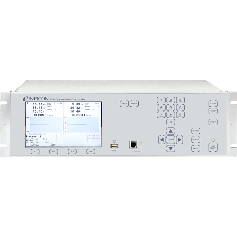
Comparing the crystal's frequency an instant ago and its current frequency, and using an appropriate algorithm, gives a measure of the mass deposited and, from the time interval, a measure of deposition rate and thickness. This is the primary information reported by a quartz crystal monitor (also known as quartz crystal microbalance) that, with a feedback loop to the deposition source power supply, becomes a quartz crystal controller. (The initials QCM used below, imply both monitors and controllers).
QCMs are used in measuring and controlling deposition rates of metal, alloys, semiconductors, and insulators. The more sophisticated models can monitor up to six separate crystal sensors and control the deposition rate from six separate sources, one at a time. For co-deposition, up to two sources can be simultaneously controlled. However, recent developments in organic and polymeric light emitting devices (OLEDs and PLEDs) that require multiple simultaneous depositions have led to QCMs that control up to six crystals and sources simultaneously.
Making accurate and precise thickness measurements involves many subtleties some addressed by the QCM manufacturer's design, while others demand operator attention. The more constraining characteristics are listed below, together with one manufacturer's techniques to overcome the constraints.
Tooling FactorObviously, during deposition, the QCM cannot occupy the same geometric position as the substrate. But placing the QCM to one side of the vapor plume means the crystal sees a different deposition rate. The tooling factor corrects this geometric factor and is determined by calibration: (1) measuring the rate of a (stable and reproducible) thermal evaporation with the QCM in the substrate's position, and (2) measuring the rate for the same thermal evaporation with the QCM in its side-position. Because the tooling factor depends on the specific geometry of the chamber, the QCM's location, and the source's plume, this factor can only be addressed by the operator.
Acoustic ImpedanceA material's acoustic impedance, often quoted as 'Z', is density x longitudinal velocity of sound (with a numerical factor). When the Z value is compared to that of quartz (the piezoelectric material used as basis of deposition rate monitoring) it is quoted as 'Z-ratio'. The material's Z-ratio is used to correct the signal when the quartz crystal sensor is used to detect deposition rate or thickness. Tables of Z-ratio values for common materials are available on the internet or from the monitor/controller manufacturer's manual. For materials not listed, the operator should calibrated actual thickness vs measured thickness as appropriate.
Inficon™ Auto Z circuitry
Unfortunately, acoustic impedance issues do not end with applying the right value. The Z-ratio changes with layer thickness and number of different material layers deposited on a single crystal. The INFICON™ Auto Z circuitry monitors and stores the crystal's history and applies corrections for total thickness and layer changes. Results for In/MgF2 indicate that, at total thicknesses approaching 20 micrometers, the uncorrected error per layer exceeds 20%, while the error with Auto Z is ~0%.
Mode Hopping
Crystals only accept a certain mass of deposited material before they no longer oscillate appropriately. When they reach their limit, they may cease operation, jump to a harmonic frequency, or start oscillation in another (nonfundamental) mode, hence the term mode hopping. Hopping occurs only when deposition is occurring and causes a step-change in frequency. The thickness monitoring circuitry, designed to recognize incremental frequency changes, is unable to resolve the information and fails, causing ruined products and wasted time. Although "certain mass" implies a known mass, this is not the case. An individual crystal's mass load before it starts mode hopping is unpredictable.
Inficon's patented ModeLock™ technology
As explained earlier, in a conventional QCM the crystal determines the RF power supply's frequency the crystal's free-running resonant frequency. Mode hopping limits the crystal's life and failure invariably occurs during deposition.
INFICON's patented ModeLock™ technology overcomes this failure mode. It forces the crystal to remain in its fundamental frequency for its useful life, extends that life to a known cut-off point, virtually eliminates mode hopping, and gives crystal-frequency data of a higher precision than conventional QCM systems.
ModeLock uses a separate, internal oscillator for the RF and drives the crystal by delivering a packet of fixed-frequency sine waves. Then, through a feedback link, the phase and voltage characteristics of the crystal's return signal are examined. When the phase between the outgoing packet and incoming signals changes, the ModeLock circuitry corrects the frequency of the next packet to match the crystal's new resonant frequency. With an update rate of 0.15 MHz (roughly every 7 microseconds), ModeLock response time is much faster than significant film thickness changes.
Crystal Sensors
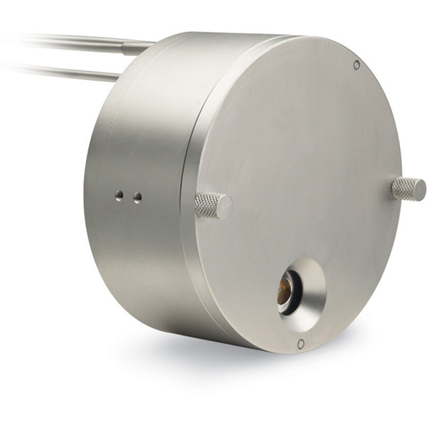
While the "traditional" water-cooled housing with a single crystal is still the standard for monitoring depositions in R&D evaporations, a variety of crystal sensors have been developed for process applications. Sensors carrying multiple crystals provide backup should one crystal fail, or are used separately during sequential multi-component depositions. The "next" crystal is either rotated from a covered position into the active position or uncovered by flipping a shutter.
Sputtering Sensors
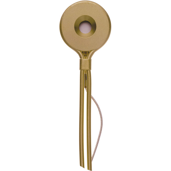
A sputter deposition process is an electrically noisy environment. The crystal sensor recommended for some sputtering applications is housed in gold-plated beryllium copper (beryllium copper to maximize heat removal, and gold-plated to aid in corrosion resistance). This sensor also features a permanent magnet behind the crystal to divert electrons escaping from the plasma that could impinge on the sensor, in turn raising the temperature and causing erratic thickness measurements.
Power Supplies
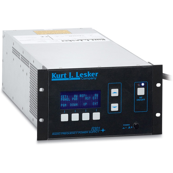
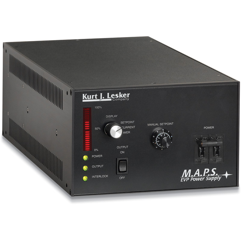
The generic term "power supplies" covers a whole array of products. Here, the scope is limited to supplies used in thin film deposition— more specifically, to the processes of thermal evaporation and sputtering. The information needed before selecting and installing a power supply for thermal evaporation is not extensive. By contrast, selecting and installing an RF power supply for sputter deposition requires a reasonable understanding of: RF transmission, RF grounding, maximizing RF power transfer to plasmas using auto impedance matching tuners, RF plasma potentials, DC self-biasing, and potential drops between the plasma and grounded/capacitively coupled electrodes. While relevant, these issues are too complex for these notes.
RF Supplies
In the context of thin film technology, RF power is used (a) to sputter poorly conducting or insulating targets; (b) for plasma cleaning of substrate or chamber surfaces; (c) to apply a DC bias to a substrate; and (d) to sputter metals and other conductors. (As noted in the introduction, only brief explanations are given here.)
Sputtering Insulating TargetsAttempting to sputter an insulating target with DC power by putting a negative DC potential on a (conducting) base-plate behind the target causes the plasma's positive ions to bombard the target's surface. Since its resistance prevents electron flow from the base-plate, the ion charge is not neutralized and the target's surface quickly reaches a high positive voltage, stopping further ion bombardment.
If the base-plate is RF powered, during the negative half-cycle ions bombard the target and sputtering occurs. During the positive half-cycle, electrons bombard the target and neutralize the ion charge. As is clear, sputtering occurs half the time power is applied, leading to relatively low sputter rates.
Plasma CleaningFilm adhesion to any substrate's surface is, in part, determined by the surface's cleanliness. Adsorbed vapors and contaminants must be removed just before film deposition begins. One method is to position an (moveable under-vacuum) electrode to face the substrate and apply an RF voltage. In the best arrangements, the electrode is hollow and connected to a gas supply. Tiny holes in the side facing the substrate provide the gas flow in which the plasma is lit and with which desorbed products are carried to the pumps. Removing vapors from the chamber's inner surfaces require a more "global" plasma made by an RF voltage on a central electrode in a low pressure gas flow.
Substrate DC BiasWithout attempting to describe details, the substrate can be maintained at a negative potential with respect to the plasma. This prevents electron bombardment but allows ion-bombardment from the plasma.
Sputtering MetalsGiven the lower sputter rates of metals using RF, the question is: Why do this? The answer is implicit in the previous paragraph. In effect, this gives ion-assisted deposition (see the technical notes in Section 15) without an additional ion source. Metal films deposited with RF power tend to have better adhesion and a more compacted morphology compared to similar films made using DC power.
DC Supplies
Conducting (and some semiconducting) targets are sputtered, often at high rates, with DC power supplies. The wiring of source and supply are simple interconnections because there are no plasma impedance matching issues. However, it is not possible to use "any" DC power supply for sputtering. As a minimum, the supply should: (a) have a high maximum voltage (1 kV or higher) to start the plasma, (b) give 100% of its rated power at any voltage throughout its total range, not just at some optimum design voltage, (c) detect arcs and quickly suppress them, (d) have its output switchable to constant power, constant voltage, or constant current, and (e) have the selected power output controllable by an analog signal feedback from a thickness monitor.
Pulsed DC Supplies
Using DC supplies for reactive sputtering (conductive metal target and active gas such as O2 to produce oxide films) often leads to the target surface being 'poisoned' with an oxide layer that stops the sputter process. Using RF power supplies is an option but the reduced sputtering rate of RF sputtering is sometimes unacceptable.
A better solution in terms of sputter rate and control of the deposition is obtained by using a pulsed power DC supply. Such supplies provide a negative voltage to the target that is reversed (to a positive voltage) with a variable frequency and variable duration. Target is sputtered during the negative voltage cycle but any high resistivity oxide formed on the surface is neutralized during the voltage reversal.
Pulsed DC supplies have user-adjusted negative voltage output and positive voltage reversals (that reach about 10% of the set voltage in the positive direction). The voltage reversal can be varied for frequency and duration (duty cycle) over some appropriate range. The reversal switch time is fast to prevent plasma collapse. By varying voltage, frequency, and duty cycle optimum sputtering conditions for a particular target material can be found.
AC Supplies
A variety of AC power supplies are needed for applications such as: Resistively heating various sources for evaporating materials, substrate temperature control, and internal chamber back-out heaters.
Boats, Boxes, Filaments, Baskets, etc.Thermal evaporation sources, shown in Evaporation Sources, are resistively heated refractory metal boats, boxes, filaments, etc. powered by a variable high-current, low voltage supplies. To get the source to the appropriate evaporation temperature for the material of interest, power supplies are built to deliver 2kW, 4kW, or 6kW. The maximum current available depends on maximum power output and the voltage tap selected on the transformer secondary. For example, the 2kW power supply has 5V, 10V, 20V, and 40V taps giving max currents of 400A, 200A, 100A, and 50A respectively.
Effusion Cells - High TemperatureAn effusion cell is a crucible surrounded by tungsten filament heater coil. It needs relatively low voltages and modest currents to reach (maximum) operating temperatures (~1,500°C). A controllable power supply able to deliver 40 amps at 24 volts is sufficient for many effusion cell designs. Such cells, and power supplies, are used in applications where high melting point metals and compounds are evaporated.
Effusion Cells - Low TemperatureThese are constructed like the high temperature effusion cells, but the temperature range of interest is 100°C to 500°C for evaporating organic or high vapor pressure inorganic materials. The allowable temperature error in absolute degree terms is very stringent, and precise control demands special circuits to minimize temperature overshoots and undershoots. Typical power supplies for this application have outputs of 15 amps at 12 volts.
Substrate/Bakeout HeatersThe most frequently used heater types for these applications are quartz halogen lamps or resistance heaters made from bare Kanthal®, nichrome, or other resistance wire. Such heaters are usually made to operate at standard line voltage (115 and 240VAC being common) and need power supplies with controlled outputs at that line voltage.
Contact us by clicking here for more information and to discuss your specific process application requirements.
