Ytterbium Fluoride (YbF3) Pieces Overview
We sell these pellets and pieces by unit weight for evaporation use in deposition processes. These approximate materials prices are published to provide budgetary guidelines. Actual prices can vary and may be higher or lower, as determined by availability and market fluctuations. To speak to someone directly about current pricing, please click here .
Ytterbium Fluoride (YbF3) General Information
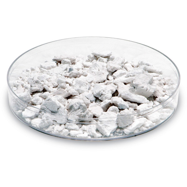
Ytterbium fluoride is an inorganic chemical compound with a chemical composition of YbF3. It is white and crystalline in appearance with a melting point of 1,157°C and a vapor pressure of 10-4 Torr at ~800°C. Users of ytterbium fluoride will utilize it in place of thorium fluoride (ThF4) which is radioactive. It is evaporated under vacuum for the production of IR lasers and filters.
Ytterbium Fluoride (YbF3) Specifications
| Material Type | Ytterbium Fluoride |
| Symbol | YbF3 |
| Color/Appearance | White, Crystalline Solid |
| Melting Point (°C) | 1,157 |
| Theoretical Density (g/cc) | 8.2 |
| Thermal Evaporation Techniques |
Boat: Mo |
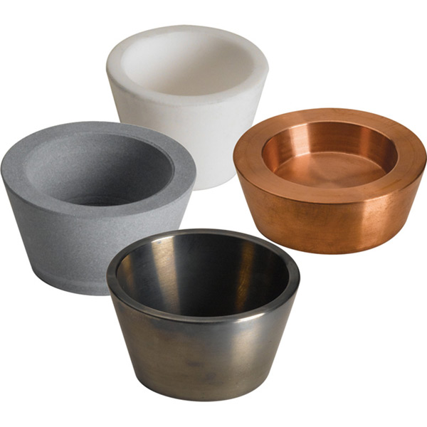
| E-Beam Crucible Liner Material | Tantalum, Molybdenum |
| Temp. (°C) for Given Vap. Press. (Torr) | 10-4: ~800 |
| Suggested QCM Crystal | Alloy Crystal: 750-1002-G10**** |
**** Suggestion based on previous experience but could vary by process. Contact local KJLC Sales Manager for further information
Empirical Determination of Z-Factor
Unfortunately, Z Factor and Shear Modulus are not readily available for many materials. In this case, the Z-Factor can also be determined empirically using the following method:
- Deposit material until Crystal Life is near 50%, or near the end of life, whichever is sooner.
- Place a new substrate adjacent to the used quartz sensor.
- Set QCM Density to the calibrated value; Tooling to 100%
- Zero thickness
- Deposit approximately 1000 to 5000 A of material on the substrate.
- Use a profilometer or interferometer to measure the actual substrate film thickness.
- Adjust the Z Factor of the instrument until the correct thickness reading is shown.
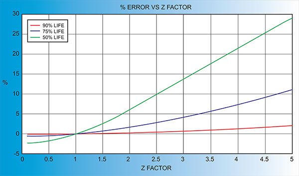
Another alternative is to change crystals frequently and ignore the error. The graph below shows the % Error in Rate/Thickness from using the wrong Z Factor. For a crystal with 90% life, the error is negligible for even large errors in the programmed versus actual Z Factor.
Thermal Evaporation of Ytterbium Fluoride (YbF3)
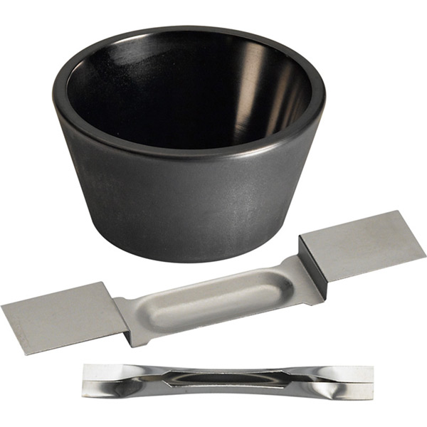
We recommend thermally evaporating ytterbium fluoride from a molybdenum boat such as our EVS8B005MO. A tantalum baffle box with a perforated top like our EVSSB2 with EVSSB2B can also be used.
Pressure should be monitored to ensure outgassing is at an acceptable level before increasing power. With an evaporation temperature of ~900°C and a base pressure for evaporation of 10-6 Torr, we anticipate a deposition rate of 10-15 angstroms per second. Film density and refractive index improve with higher substrate temperatures.
E-beam Evaporation of Ytterbium Fluoride (YbF3)
Ytterbium fluoride can be e-beam evaporated from a tantalum or molybdenum crucible liner.
We recommend sweeping the e-beam at low power to uniformly melt the material and avoid hole drilling. We suggest evaporating at a low e-beam power to avoid material dissociation. Pressure should be monitored to ensure outgassing is at an acceptable level before increasing power. We estimate a deposition rate of 10-15 angstroms per second when the evaporation temperature is at ~900°C. Under these conditions, we expect good adhesion to most substrates. Yttrium oxide (Y2O3), hafnium oxide (HfO2), or aluminum oxide (Al2O3) can be used as a thin adhesion layer if necessary. Film density and refractive index improve with higher substrate temperatures.
Another key process note is to consider the fill volume in the e-beam application because we find that the melt level of a material in the crucible directly affects the success of the crucible liner. Overfilling the crucible will cause the material to spill over and create an electrical short between the liner and the hearth. The outcome is cracking in the crucible. This is the most common cause of crucible liner failure. Placing too little material in the crucible or evaporating too much material before refilling can be detrimental to the process as well. When the melt level is below 30%, the e-beam is likely to strike the bottom or walls of the crucible which immediately results in breakage. Our recommendation is to fill the crucible between 2/3 and 3/4 full to prevent these difficulties.
Crucible liners should be stored in a cool, dry place and always handled with gloves or forceps.
See highlighted results that match your result in the table below.
Ordering Table
| More Info | Material | Description | Size | Quantity | Purity | Color | Part Number | Price | In Stock | Add To Cart |
|---|---|---|---|---|---|---|---|---|---|---|
| More Info | Material | Description | Size | Quantity | Purity | Color | Part Number | Price | In Stock | Add To Cart |
| Ytterbium Fluoride |
YTTERBIUM FLUORIDE PIECES , |
1mm - 6mm | 500 g | 99.90% | White to Grey | EVMYBF301-6MMPMT | P.O.R. |
|
||
| Ytterbium Fluoride |
YTTERBIUM FLUORIDE PIECES, |
1mm - 6mm | 50 g | 99.9% | White to Grey | EVMYBF301-6MMPMB | P.O.R. |
|
