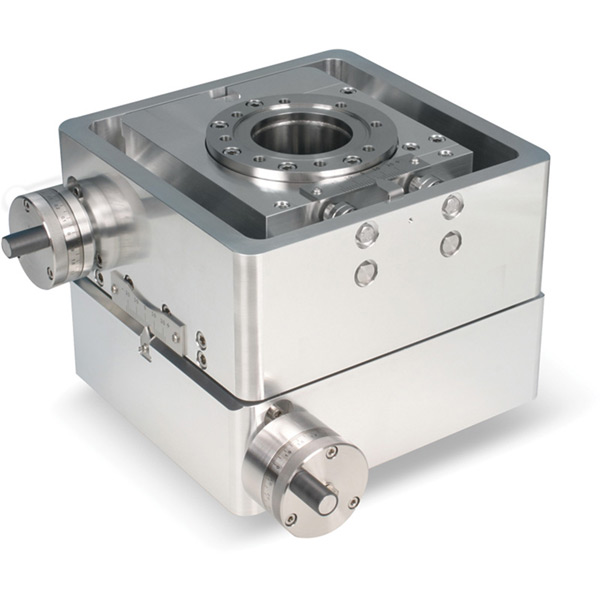
MultiBase stages provide modular platforms for the manipulation of components in the X & Y planes. A MultiBase may be used as a discrete stand-alone component or combined with our range of Linear Shift Mechanisms and MagiDrives to build a multi-axis manipulator with up to six axes of motion.
The MultiBase XY stage is the first choice for both research and demanding production environments due to its precise motion, true UHV performance, and rugged construction which allows mounting in any orientation.
The MultiBase design includes two parallel flanges. One remains fixed while the other provides the movement. A high quality, edge welded bellows spans the flanges to accommodate the required motion while ensuring an all-metal vacuum enclosure. The device works by adjusting the position of the traveling flange in relation to the fixed system mounting flange. Positioning of the traveling flange is controlled through two external lead-screws.
A kinematic mechanism ensures smooth and precise motion. This novel mechanism incorporates a high precision drive and guidance system, removing the requirement for vulnerable cross-roller slides used by other manufacturers. Combining this with a rigid construction allows mounting in any orientation without additional supports.
Scales are fitted to each axis for resolving the position of the traveling flange on the manual version. The motorized stages are fitted with stepper motor and gearbox combinations.
Features
- Up to ±31mm of X & Y Motion
- Can be mounted in any orientation
- Smooth kinematic motion
- Robust construction for high loads
Movement Diagram
Unlike some X/Y manipulators where the X/Y travel is limited by the central probe and the ID of the edge welded bellows, the MultiBase limits the X and Y travel using rigid stops, which provides a more robust design. In the context of the diagram above this means that the axis of the central probe / tube cannot pass outside the limitations of the red box, as defined by ± XMAX and ± YMAX, both given in the table below. The absolute maximum displacement from the center will be the vectorial sum of ±Xmax and ±Ymax, which is given simply by Pythagoras as:
± (XMAX2 + YMAX2) 0.5
Provided the central probe or tube has a diameter less than 'PROBE OD' (also given in the table) it will not clash or harm the bellows.
NOTE: The fixed flange is supplied with metric tapped holes as standard, clear holes are available on request.
Specifications Table
| Model/Series | XY14-64-38 | XY14-100-38 | XY31-100-38 | XY31-100-64 | XY31-150-64 |
|---|---|---|---|---|---|
| Xmax, Ymax | ±10 mm | ±10 mm | ±22 mm | ±22 mm | ±22 mm |
| XY Travel | ±14 mm | ±14 mm | ±31 mm | ±31 mm | ±31 mm |
| Probe OD | 22 mm max to achieve full movement |
22 mm max to achieve full movement |
22 mm max to achieve full movement |
22 mm max to achieve full movement |
22 mm max to achieve full movement |
| xyzActuation | Manual via combined micrometer handwheel and linear scale. Motorized units are stepper motor driven. |
Manual via combined micrometer handwheel and linear scale. Motorized units are stepper motor driven. |
Manual via combined micrometer handwheel and linear scale. Motorized units are stepper motor driven. |
Manual via combined micrometer handwheel and linear scale. Motorized units are stepper motor driven. |
Manual via combined micrometer handwheel and linear scale. Motorized units are stepper motor driven. |
|
Rear/Travel Flange |
CF38 70 mm (2.75") O.D. with M6 straddled holes |
CF38 70 mm (2.75") O.D. with M6 straddled holes |
CF38 70 mm (2.75") O.D. with M6 straddled holes |
CF64 114 mm (4.5") O.D. with M8 straddled holes |
CF64 114 mm (4.5") O.D. with M8 straddled holes |
| Mounting Flange | 114 mm (4.5") O.D. CF64 with M8 straddled holes |
CF100 152 mm (6") O.D. with M8 straddled holes |
CF100 152 mm (6") O.D. with M8 straddled holes |
CF100 152 mm (6") O.D. with M8 straddled holes |
CF150 203 mm (8") O.D. with M8 straddled holes |
|
XY Axis Resolution |
Manual drive +0.01 mm. Stepper motor driven +/- 0.005 mm |
Manual drive +0.01 mm. Stepper motor driven +/- 0.005 mm |
Manual drive +0.01 mm. Stepper motor driven +/- 0.005 mm |
Manual drive +0.01 mm. Stepper motor driven +/- 0.005 mm |
Manual drive +0.01 mm. Stepper motor driven +/- 0.005 mm |


