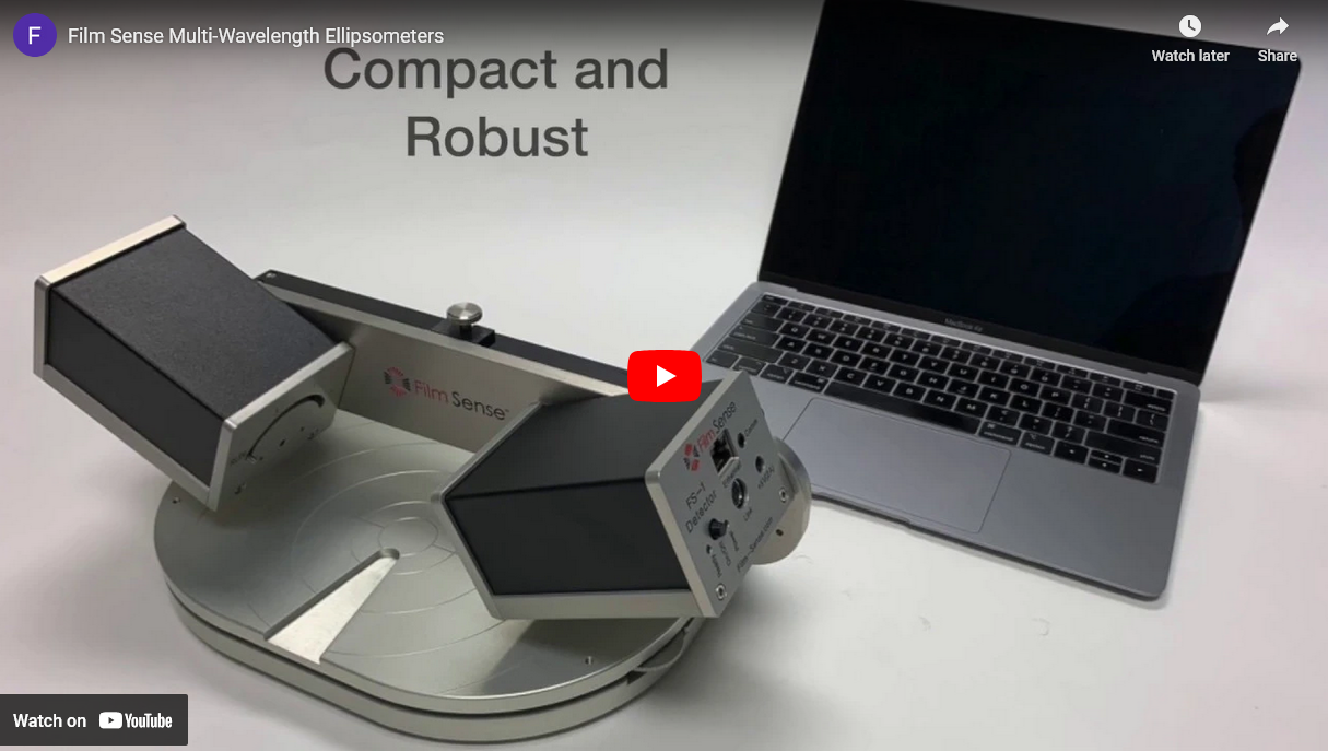
Film Sense FS-4 and FS-8 (Gen. 4) Ellipsometers
Affordable Multi-Wavelength Ellipsometer for Thin Film Measurements
Gen. 4 Design
Additional wavelengths and spectral range for the FS-8 model:
- Further enhances the measurement capabilities over a wide range of thin film applications
Same benefits of the patented Film Sense ellipsometer technology:
- Long life LED light sources
- Fast and reliable
- No moving parts detector
- Compact design
- Web browser software interface, while maintaining ease of use and affordability
Gen. 4 Common Specifications
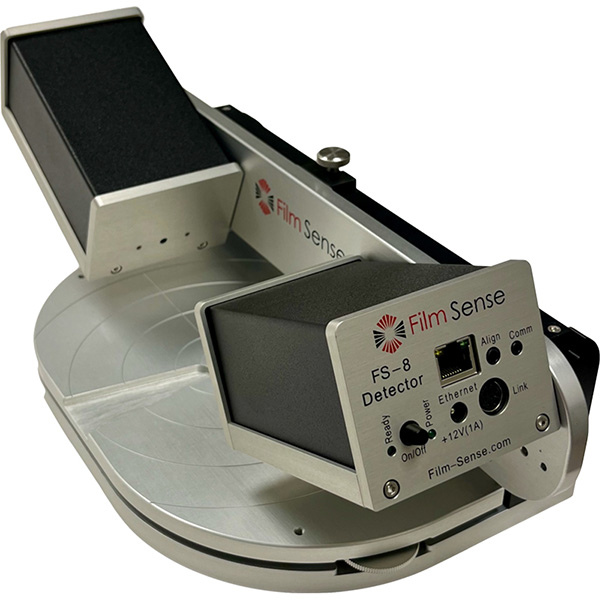
- Compact optics: Source 125 x 80 x 60mm, Detector 110 x 80 x 60 mm
- Simple connections: +12V wall plug power supply, Ethernet, and Source-Detector link cables
-
Motorized Source Polarizer:
- Provides automated instrument calibration
- Enables zone-averaged measurements, for improved measurement accuracy
- 4x more intensity (compared to original FS-1), and updated detector electronics provide improved measurement precision: 2x for ex situ, 4x for in situ
Film Sense Ellipsometer Wavelengths
| Wavelength (nm) | ||||||||||
|---|---|---|---|---|---|---|---|---|---|---|
| System | Number of Wvls | 370 | 405 | 450 | 525 | 595 | 660 | 735 | 850 | 950 |
| FS-1 (gen. 2 & 3) | 4 | X | X | X | X | |||||
| FS-1EX (gen. 2 & 3) | 6 | X | X | X | X | X | X | |||
| FS-7 (gen. 4) | 4 | X | X | X | X | |||||
| FS-8 (gen. 4) | 8 | X | X | X | X | X | X | X | X | |
FS-4 Ellipsometer
- 4 wavelengths, 450-660nm spectral range
- Excellent choice for measuring single layer transparent films in the 0-2 µm thickness range, with precision down to 0.0004 nm
- US Patent #9,354,118
Standard Ex Situ Configuration
- 65° Angle of Incidence
- Manual sample loading and height adjustment
- Sample sizes up to 200 mm dia. And 20 mm in thickness
- Sample tilt with +/-2 deg range
- Beam size on sample 4 x 9mm
- Compact footprint (180 x 400mm) and light (5kg)
FS-8 Ellipsometer
- 8 wavelengths, 370-950nm spectral range
- The UV wavelength (370 nm) provides enhanced sensitivity when measuring very thin films <10 nm
- The 3 longer wavelengths (735, 850, and 950 nm) enable the measurement of thicker transparent films (up to 5µm), and absorbing semiconductor films (such as poly-Si, SiGe, amorphous-Si, etc.)
- 8 wavelengths and wider spectral range provide enhanced measurement capability for multilayer film stacks
In Situ Capabilities
- Sub-monolayer thickness precision, in real time
- Determine deposition rates and film optical constants n&k, at multiple process conditions, without breaking vacuum
- Monitor and control the deposition of multilayer film structures
- FS-API interface for external software control (LabVIEW™ compatible)
- Applicable to most thin film deposition techniques: Sputtering, ALD, MBE, MOCVD, e beam evaporation, etc.
Mounting Specifications
- Adapters for mounting the FS Ellipsometer light source and detector units to standard 2.75" or 1.33" conflat vacuum flanges (windows not included)
- Easy to adjust tilt stages for beam alignment
- The FS Ellipsometer source and detector units are compact and light (≈1 kg each).Contact us by clicking here for more detailed mounting specifications and dimensions
- Can be installed without breaking chamber vacuum
FS Ellipsometer ALD Applications
The FS Ellipsometer Multi-Wavelength Ellipsometer is ideal for Atomic Layer Deposition (ALD) applications
- The excellent thickness precision can easily resolve the sub-monolayer thickness changes for individual ALD cycles
- The compact design simplifies the mounting and integration with ALD reactors for in situ measurements
- The in situ, real time thickness data provided by the FS Ellipsometer can significantly reduce the ALD process development time when exploring new process parameters and precursors
- If in situ measurements are not possible (ports on the ALD chamber are required to provide access for the optical beam), the FS Ellipsometer can still provide accurate ex situ thickness measurements for very thin ALD films, at an affordable price
- The FS Ellipsometer has been installed for in situ measurements on many different ALD reactors, including custom designs, and commercial reactors
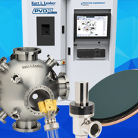
- Kurt J. Lesker ALD150LX
FS Ellipsometer Mapping Systems
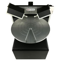
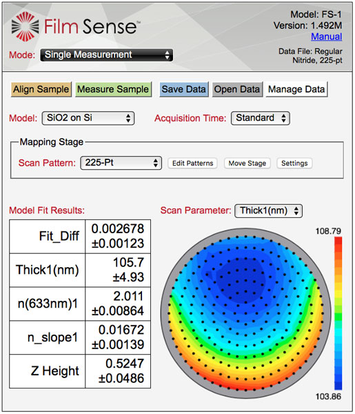
These products combine an FS Multi-Wavelength Ellipsometer with compact mapping stages to provide fast, accurate, and reliable film thickness uniformity measurements across a wafer.
FS-XY150
- Typical time for wafer map: 60 seconds (49 points on a 150 mm diameter wafer)
- Compact footprint: 600x600 mm, 16 kg
- Stage travel (X,Y): 150 x 150 mm, resolution: 5 µm
FS-RT300
- Typical time for wafer map: 90 seconds (49 points on a 300 mm diameter wafer)
- Compact footprint: 400x500 mm, 22 kg
- Stage travel: R (linear) 150 mm, resolution: 12 µm Theta (rotation) 360°, resolution: 0.1°
Features and Specifications
- 4 wavelengths of ellipsometric data (465, 525, 580, 635 nm), with long life LED sources, and no moving parts detector
- Accurate thickness measurements for most transparent thin films from 0 - 1000 nm
- Typical thickness repeatability: 0.015 nm
- Integrated focusing probes, standard spot size: 0.8 x 1.9 mm (other spot sizes available)
- Motorized Z-stage for sample auto-alignment
- Flexible Scan Pattern Editor
- Contour plots of measured parameters
Film Sense Demonstrations
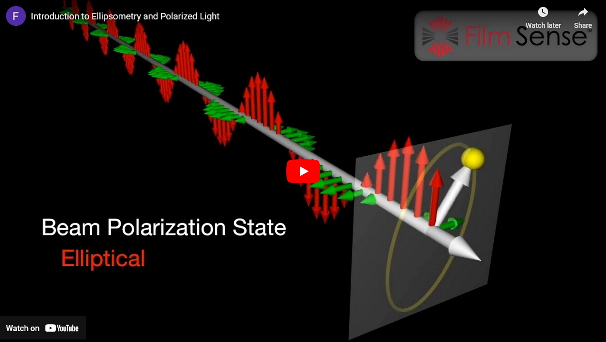
Introduction to Ellipsometry and Polarized Light
Using 3D animation, the fundamentals of polarized light and ellipsometry are presented.
FS Multi-Wavelength Ellipsometer Technology
Since ellipsometry uses polarized light, an ellipsometer system is typically a complex and expensive optical instrument. However, the FS Multi-Wavelength Ellipsometer hides the complexity from the user, packaging powerful multi-wavelength ellipsometer technology into a compact, robust and affordable sensor, and enabling quick and accurate ellipsometric measurements. With the FS Ellipsometer, you do not need to understand the details of how the ellipsometric measurement is made, and operating the sensor is simple. Some of the innovative features which are incorporated into the FS Ellipsometer are described below.
Light Source
The FS Ellipsometer Light Source Unit provides the Polarization State Generator for the ellipsometer system. 4 visible Light Emitting Diodes LED's (blue, green, yellow, and red) are used as light sources. LED's are an ideal light source for an ellipsometer system. The only down side to using LED's as a light source is their wide spectral bandwidth, but this is accurately and automatically corrected for in the FS Ellipsometer data analysis procedure*. Since they have long lifetimes (>50,000 hours), the FS Ellipsometer LED's never need to be replaced or realigned over the lifetime of the instrument. In operation, the 4 LED's are sequentially scanned in less than 10 ms to provide ellipsometric data at 4 wavelengths essentially simultaneously. The internal optics of the FS Ellipsometer Light Source Unit* combine the light from the 4 LED's into a common beam, which is bright and uniform. The FS Ellipsometer Light Source Unit also includes a Polarizer mounted on a manual rotation mechanism. In normal operation, the Polarizer is left at a fixed position. To calibrate the orientation of the Source and Detector units to the sample, the Polarizer is manually rotated to 4 positions. This simple calibration procedure takes only a few seconds, and only needs to be done when the Source and Detector units are mounted on a process chamber for in situ measurements, or when the Source and Detector units are remounted to the ex situ measurement Frame.
Detector
The FS Ellipsometer Detector Unit provides the Polarization State Detector for the ellipsometer system. The FS Ellipsometer Detector design has no moving parts, and is based on the Division of Amplitudes Polarimeter (DOAP) concept first proposed by Azzam ("Division-of-amplitude photopolarimeter (DOAP) for the simultaneous measurement of all four Stokes parameters of light", R. M. A. Azzam, Opt. Acta Vol. 29, page 685, 1982). One disadvantage of the traditional DOAP design is that the polarization measurement accuracy can be affected by the alignment and uniformity of the incoming beam. To overcome this disadvantage, the FS Ellipsometer Detector implements a novel optical configuration* to cancel measurement errors caused by mis-alignment or uniformity of the measurement beam. Since there are no moving parts, the ellipsometric data can be acquired very quickly (10 ms minimum acquisition time for 4 wavelengths of data), and long term measurement stability and robustness is also improved. The computer which controls the data acquisition and performs the data analysis is also integrated into the FS Ellipsometer Detector Unit, resulting in a compact sensor that requires no additional control electronics.
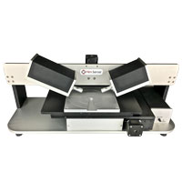
For typical measurements, the FS Ellipsometer Light Source and Detector units are mounted on the standard frame. This frame can accommodate samples up to 200 mm in diameter, up to 23 mm in thickness, and it provides manual height adjustment for the sensor units with respect to the sample surface. Custom attachments can be added to the frame, and the Light Source and Detector units can be attached to a custom frame ( Contact Us for CAD drawings for custom interfacing or OEM applications). Standard options for in situ mounting, focusing, and more, are also available (see Products page).
* US Patent #9,354,118
The FS Ellipsometer uses the power of ellipsometry to optically characterize samples. In an ellipsometer system, the Polarization State Generator (PSG) emits light with a known polarization, which is obliquely incident on the sample, and the Polarization State Detector (PSD) measures the polarization state of the light reflected from the sample.
The change in polarization state caused by the sample reflection can be defined by the ratio of the sample reflectivity for p-polarized light (Rp), over the sample reflectivity for s-polarized light (Rs). This ratio is a complex number, which is typically denoted by ρ (rho), and is often reported in terms of the ellipsometric parameters Ψ (Psi) and Δ (Delta), as defined by the following equation. According to this equation, tan(Ψ) defines the magnitude of the reflectivity ratio for p- and s- polarized light, and Δ defines the phase difference between the reflected p- and s- polarized light.
An alternate representation of the ellipsometric parameters is shown below. The N, C, and S ellipsometric parameters can be calculated in terms of the Ψ (Psi) and Δ (Delta) parameters, assuming the sample is isotropic and non-depolarizing. One of the advantages of the N,C,S representation of the ellipsometric parameters is that if the sample is depolarizing, the degree of polarization P can also be reported.
The ellipsometric parameters measured on the sample (and reported in either the Ψ/Δ or N,C,S representation) can be further analyzed to determine sample properties of interest, such as film thicknesses and optical constants.
Core Technology: Multi-Wavelength Ellipsometry
- More powerful than single wavelength ellipsometry or reflectometry
- Much less cost/complexity compared to spectroscopic ellipsometry
- Innovative technology (U.S. Patent Number 9,354,118)
Easy To Use Software
The FS Ellipsometer software uses a web-browser based user interface, and does not require any software installation on the controlling computer. Any desktop, laptop, tablet, or even smart phone that runs a modern web browser can be used to control and operate the FS Ellipsometer Multi-Wavelength Ellipsometer. Computers can be directly connected to the FS Ellipsometer by a standard Ethernet cable, or by connecting the FS Ellipsometer to a wireless router, devices can access the FS Ellipsometer via WiFi. The FS Ellipsometer software provides easy to use Modes for performing single, continuous, and dynamic measurements, calibrating and testing the sensor, and building and testing data analysis models.
To determine sample properties of interest (such as layer thicknesses, optical constants, etc.), it is necessary to analyze the measured ellipsometric data. The FS Ellipsometer software implements the traditional model-based, least squares analysis approach, encapsulating and hiding all the necessary thin film optics calculations and non-linear regression algorithm behind an easy to use interface. Models are built by simply selecting materials for the substrate and layer(s), and defining model fit parameters (such as layer thicknesses, angle of incidence of the measurement beam, index of refraction, etc.). Clicking the "Fit Data" button invokes the regression algorithm, which automatically adjusts the model fit parameters to minimize the difference between the model calculated and measured ellipsometric data, resulting in the "best fit" values for the fit parameters. To improve the convergence of the model fit, minimum and maximum bounds can be specified for the fit parameters, and to achieve global convergence with wide parameter bounds, starting increments for parameters can also be specified. The Model Validator™ button automatically tests the model to verify convergence, and estimates the precision in the sample fit parameters for a typical FS Ellipsometer measurement.
The FS Ellipsometer software also provides advanced features, such as Trajectory Analysis for determining a consistent set of optical constants for ellipsometric data acquired on a series of samples with a range of film thicknesses (as is often the case when performing in situ ellipsometry measurements during the film deposition process). A Film Sense Application Programming Interface (FS-API) is also available, to support the integration of the FS Ellipsometer Thin Film Sensor with process control computers and PLC's, and to enable the creation of customized data acquisition software.
