Evaporation Sources
Evaporation occurs when the atoms/molecules of the material being evaporated achieve sufficient energy to overcome the solid/liquid binding forces and enter the gas phase. To increase the evaporation rate, the average energy is increased by raising the evaporant's temperature. Expressed another way, raising its temperature increases an evaporant's vapor pressure (VP).
It's a common misconception that a solid has no VP, but as it melts, vapor suddenly appears. Melting has nothing to do with vapor pressure! For all materials (that do not decompose) VP versus temperature is a smooth curve with the material's melting point being at just one point on that curve. Honig and Kramer's Vapor Pressure Data for the Liquid and Solid Elements (RCA 1969) clearly shows the non-relationship between VP and melting point.
The most striking examples are two pairs of metals: gallium/gadolinium and magnesium/aluminum. The first pair have melting points of 29.76°C (Ga) and 1312°C (Gd). Yet their VPs are within a factor of 10 from 10-11 Torr to 760 Torr. The second pair's melting points are 650°C (Mg) and 660.32°C (Al). However, Mg's VP is > 107 higher than Al's VP at any temperature.
The strict relationship between VP and temperature for each evaporant has at least one important consequence when evaporating alloys or mixtures. Except in rare circumstances, it's impossible to evaporate an alloy and make a film of identical stoichiometry. For example, evaporating 20/80 Sn/Pb solder gives, initially, a film of almost pure Pb since its VP is 106 times higher than Sn's. (Dilution and activity coefficient affect the vapor composition too, but these issues are beyond this simple introduction.)
When evaporating compounds, there are few general rules. Some compounds (e.g., MgF2 and KI) evaporate as molecules and the film's stoichiometry is identical to the compound's. Oxides may: dissociate completely, evaporate as lower oxides, evaporate as non-stoichiometric oxides, or give films with compositions identical to the evaporant. Compound semiconductor materials, the so-called III-V, II-VI materials, present a complex mix of results. Individual components may evaporate as dimers or tetramers, depending on the temperature (again, concepts beyond this simple introduction).
Heating Methods
Four heating techniques are commonly used to evaporate materials for thin film deposition. Different names may be applied but generally they are known as:
- Direct resistive heating
- Indirect resistive heating
- E-beam evaporation
- Pulse laser deposition (or ablation)
Direct Resistive Heating Thermal Sources
The evaporant is placed on/in a refractory metal source through which a high electrical current flows. The method's low equipment costs are balanced by the difficulty of maintaining a constant evaporation rate (when compared with other techniques) and possible reactions between evaporant and boat material. These devices are often called thermal sources and are essentially open heaters frequently without thermal radiation shielding, insulation, or any tricks to reduce thermal gradients.
Filaments
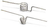
Single- or multiple-strand tungsten wire is bent into a shape (loop, point, coil) that suits a particular mounting or the required evaporation pattern. Evaporant is deposited on the wire by dipping into a melt, into a solution of a thermally degradable salt, or physically capturing pieces. The material's evaporation rate is varied by changing the current. If the material wets or alloys with the heater, non-reproducible or continuously changing evaporation rates may occur. Since this source is inexpensive, it is often used once and discarded.
Basket Heaters
If a refractory metal wire is shaped into an inverted conical basket, larger "pieces" of material can be inserted into the cone. These are also used to heat small crucibles.
Boats and Boxes
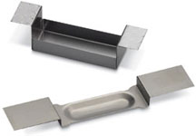
Thin, flat tungsten, tantalum, or molybdenum sheets are formed into shapes with creases, dimples, folds, bends, etc., to hold evaporant. The complexity ranges from a dimple in a strip to multi-chamber baffled boxes with sideways pointing vapor chimneys. The "baffle" in a baffle box prevents a line-of-sight between evaporant and substrate. This type of source is used where the evaporant is known to "spit" (crepitate).
Coated Boats
A coated boat has a thin coherent layer of aluminum oxide covering the dimple. These boats are sometimes recommended for applications where the hot evaporant reacts with refractory metals.
Rods & Screens
For specific applications, thick tungsten rods and fine meshes/screens are recommended. Chromium evaporation is one common example. The thick rod has lower resistance than a filament, making it easier to control lower evaporating temperatures. Meshes are sometimes used to extend the coverage area without moving the substrate.
Indirect Resistive Heating Thermal Sources
With indirect resistive heating, a crucible holds the evaporant in isolation from the heater filament. The increased thermal mass and the evaporant/heater separation stabilizes the evaporation rate. Various iterations of these indirectly heated devices are called Knudsen cells, K-cells, effusion sources, diffusion cells, evaporation cells, etc.But distinctions between these names are blurring as manufacturers explore designs that use features from several devices.
Knudsen Cells
Where repeatable, constant evaporation rates are required, Knudsen cells are chosen. The classic Knudsen cell is a large-mass, small-volume tungsten container with a close-fitting thick lid where an inverted conical-shaped aperture is bored. The container is mounted on tungsten needle points to reduce thermal losses and surrounded by tungsten heater filaments and diffusers to ensure a uniform temperature. Outside the heaters, several layers of reflective radiation shielding further reduce thermal gradients in the cell.
With the cell maintained at a uniform, constant, and known temperature, the evaporant's equilibrium vapor pressure is known. The aperture is small so the vapor lost through it does not significantly affect the cell's internal pressure, and the evaporant's effusion rate is constant. In addition, the small aperture means the vapor emerges in a cosine distribution (the flux issuing at any given angle to the cell lid's normal is proportional to the cosine of that angle). The maximum temperature for the classic Knudsen cell is around 2000K to 2100K.
Evaporation Cells
Evaporation cells are based on the Knudsen cell design but are/have:
- Less mechanically complex
- Easier to fill
- Larger capacities
- Larger orifice diameters to increase material flux
- Lids or vapor shutters
- Less stringent thermal gradient specifications
- Higher deposition rates
These devices are known as K-cells, effusion cells, evaporation sources, or thermal sources. Although the vapor plume does not have a cosine distribution, these source have many thin film applications, including molecular-beam epitaxy, low temperature evaporation (100–500°C) for organic compounds, and high temperature evaporation (1500°C) for metals and inorganic compounds.
Some heaters are flat ribbons arranged parallel to the crucible's long axis. This helps reduce temperature gradients in the important central zone. In other designs, the heater wires are more closely spaced at the crucible's ends to combat thermal end-effects.
The crucible is typically a pure alumina cylinder closed at one end with a wide bore to increase the vapor flux. This source is well-suited to conventional evaporation but some low thermal mass versions are used as flash evaporators.
Thermal Sources
Some thermal sources described in Direct Resistance Heating can be constructed to accommodate crucibles and, therefore, fit in this section. In particular, refractory metal wire baskets or refractory metal boxes can be shaped into truncated cones of appropriate depth and slope to suit a given crucible. While such heaters lack the refinements and end-effect correction found in the evaporation cells, they provide inexpensive approaches to film deposition of materials that can't be in direct contact with a refractory metal.
E-Beam Sources
The electron-beam (e-beam) source's high deposition rates and large evaporant capacity make it convenient for production-scale coating machines. Solid evaporant such as powder, granules, lumps, or shaped starter sources, is placed in the source's copper hearth or in a hearth crucible liner. A high electron flux generated by a hot filament placed below the source is electrostatically and magnetically focused on the top of the evaporant. The electron beam's energy raises the evaporant's surface temperature. Often the beam is rastered to increase the evaporation area. Since the evaporation area is surrounded by cooler (often solid) evaporant, unlike other thermal sources, the e-beam source's vapor plume is largely uncontaminated by crucible liner material.
Production scale e-beam sources are usually single pocket (one hearth). Multi-pocket source (4 or 6 hearths) are available for R&D applications. A cover plate obscures the pockets "not-in-use" to prevent vapor cross-contamination. Multi-pocket sources are particularly convenient when depositing multilayer films on a single substrate.
The drawbacks of e-beam evaporation are similar to those of thermal evaporation but they are more apparent in the e-beam source — the source must be mounted upright (to prevent the evaporant spilling), evaporants often "spit" and must be heated in a series of ramp/soak steps to evaporation temperature, and the melt presents a high-temperature source that thermally radiates the substrate.
Pulse Laser Deposition (PLD) Sources
PLD uses repetitive pulses from a laser of appropriate power density, angle of incidence, and wavelength to ablate a localized area of evaporant into a vapor plume. The wavelength is important to maximize photon absorption rather than reflection. The flash evaporation nature of this technique, at least in the small volume in which the laser pulse's energy is dumped, is advantageous when evaporating alloys or mixtures. The vapor plume tends to be stoichiometrically similar to the bulk; however, the PLD vapor plume is not particularly convenient because its flux distribution is closer to cos6 to the evaporant's surface normal.
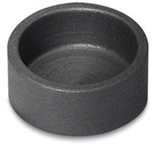
Crucible and Liners
The crucible and liners are used to (A) keep the e-beam hearth free of evaporants or (B) to act as the evaporant container for basket or foil thermal sources. For an e-beam source, a liner provides an often unrecognized benefit—an efficient thermal barrier. The same deposition rate requires only 1/4 the power needed if a liner is not used. This reduces operating costs and lowers the system's thermal burden; however, any liner must be electrically conductive to dissipate the electron charge. For a thermal source, the crucible thermal resistance is a serious but unavoidable disadvantage. The heater is usually much hotter than the evaporant's average temperature.


